 THE THIRD RAIL SYSTEM
ON THE NEW HAVEN RAILROAD.
THE THIRD RAIL SYSTEM
ON THE NEW HAVEN RAILROAD.
Scientific American—July 12, 1897
The third rail system of electric traction is now in permanent
operation on an important section of a leading steam railroad.
The recent opening of the line from Berlin to New Britain and
from New Britain to Hartford, while it is by no means the first
successful operation of third rail traction, is notable as being
its first application in a permanent way to the lines of a standard
steam railroad.
The first extensive test of this system took place within the
grounds of the World's Fair, at Chicago, where its operation was
very satisfactory. It was then adopted on the elevated roads of
Chicago, where it has given reliable service. The Brooklyn Bridge
trustees decided that it was adapted to the requirements of bridge
traffic, and laid a third rail on the outside of the tracks. The
equipment has given a good account of itself, especially in the
switching operations at the terminal stations.
It is stated by Col. N. H. Heft, chief of the electrical department
of the New York, New Haven & Hartford Railroad, who has afforded
us every facility in the preparation of the present article, that
the probability of electricity entering largely into the operation
of steam railroads was suggested to the directors by Mr. Clark
in his annual presidential report made in 1891. It was natural
that the attention of this company should be turned to the question
of electric traction, for the reason that their passenger traffic
was being exposed to severe competition from the network of suburban
and interurban trolley lines which have sprung up throughout the
country served by the New Haven road. Fully one-half of the gross
receipts of this road is realized from passenger traffic and a
large proportion of this is obtained from local traffic, of a
character for which suburban trolley car service has most attraction.
The first step taken by the company was to form an electrical
department, and give orders for the electrical equipment of a
stretch of their road which runs from Nantasket Junction to Pemberton,
Mass. This equipment, which is commonly known as the Nantasket
Beach line, was put in operation in 1895. Overhead conductors
were used and the experiment was highly successful. The company
then determined to test the third rail system of transmission,
and a trial line was laid down in 1896, when an additional 3½
miles of road was placed in service. The operations at Nantasket
were regarded by the company as being experimental and preparatory
to a further extension of the system. The results were so promising
that it was determined to apply the system on a larger and more
permanent scale, embodying in the new line the results of previous
experiments.
 The equipment
which has recently been put in operation is applied to two lines
of steam railroad, one extending from New Britain to Berlin and
the other from Hartford to New Britain, the total length of the
line from Hartford to Berlin being 12.3 miles. The equipment
which has recently been put in operation is applied to two lines
of steam railroad, one extending from New Britain to Berlin and
the other from Hartford to New Britain, the total length of the
line from Hartford to Berlin being 12.3 miles.
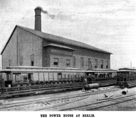
The power station has been built with a view to its enlargement
as the electric equipment is extended. The building shown in the
accompanying engraving is 106 feet wide by 117 feet in length,
the end on which the extension will be added being temporarily
walled in with wood planking. The present building contains two
stories in the front devoted to the engine and generators, etc.,
and a boiler room in the rear extending the full height of the
building. A 1,200 horse power engine is already in place and the
foundations have been built for a second. There is room in the
building for a third engine when the extension of the line calls
for it. Further details regarding the engines and the boilers
will be given in a later issue. The engine is direct connected
to a General Electric Company's standard 10 pole, 850 kilowatt
generator of the well known ironclad type, which furnishes current
at 600 volts no load and 650 volts full load.
The third rail conductor is of a special section rolled for
this purpose. It resembles somewhat a flattened A,
the flanges forming a protection to the insulating blocks upon
which it is laid. The rail is heavy, weighing ninety-three pounds
to the yard, and it is found that wooden blocks saturated with
insulating material give excellent service, and three to the rail
are found to be sufficient. The flanges of the rail come within
1½ to 1-five-eighths inches of the top of the ties, the
head of the rail being one inch higher than the main rails. It
will be seen that this conductor is carried much lower than that
on the Nantasket line, the difference being due to the height
of the main rails. The ends of the rail are bonded by sheet copper
plates one-eighth inch thick, 4½ inches wide and 12 inches
long, which are held against the under side of the flanges at
the rail ends by iron plates. The latter are bolted to each rail
by sixteen bolts, eight for each plate, the copper bonds being
sandwiched between the iron plates and the rail. The capacity
of each bond is 900,000 circular mils, the double bond having
more than the carrying capacity of the rail itself.
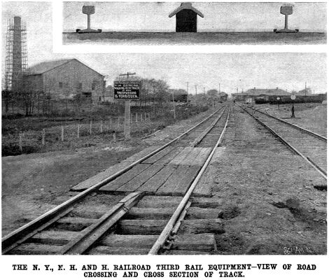 On the whole
line there are twenty-two grade crossings, at each of which the
third rail is replaced by underground cables of 850,000 circular
mils. The cables are drawn into creosoted wooden conduits filled
with an insulating material made of residuum and asphalt. The
conduits are laid in creosoted wooden troughs filled with the
same material, which are buried in the earth. Special attention
has been paid to the return circuit, as it is the opinion of Col.
Heft that the importance of this element is too often overlooked
in the construction of electric roads. The company has put in
leaf bonds of 550,000 circular mils, and these are attached to
the base of the rail in preference to the web, and are secured
by wedge fastenings. In order to prevent any interruption to the
current when a train is passing over switches and crossings a
shoe is provided on the rear car of a two-car train. This insures
that connection will be made by the shoe of the motor car before
the shoe of the second car has entered the gap. On the whole
line there are twenty-two grade crossings, at each of which the
third rail is replaced by underground cables of 850,000 circular
mils. The cables are drawn into creosoted wooden conduits filled
with an insulating material made of residuum and asphalt. The
conduits are laid in creosoted wooden troughs filled with the
same material, which are buried in the earth. Special attention
has been paid to the return circuit, as it is the opinion of Col.
Heft that the importance of this element is too often overlooked
in the construction of electric roads. The company has put in
leaf bonds of 550,000 circular mils, and these are attached to
the base of the rail in preference to the web, and are secured
by wedge fastenings. In order to prevent any interruption to the
current when a train is passing over switches and crossings a
shoe is provided on the rear car of a two-car train. This insures
that connection will be made by the shoe of the motor car before
the shoe of the second car has entered the gap.
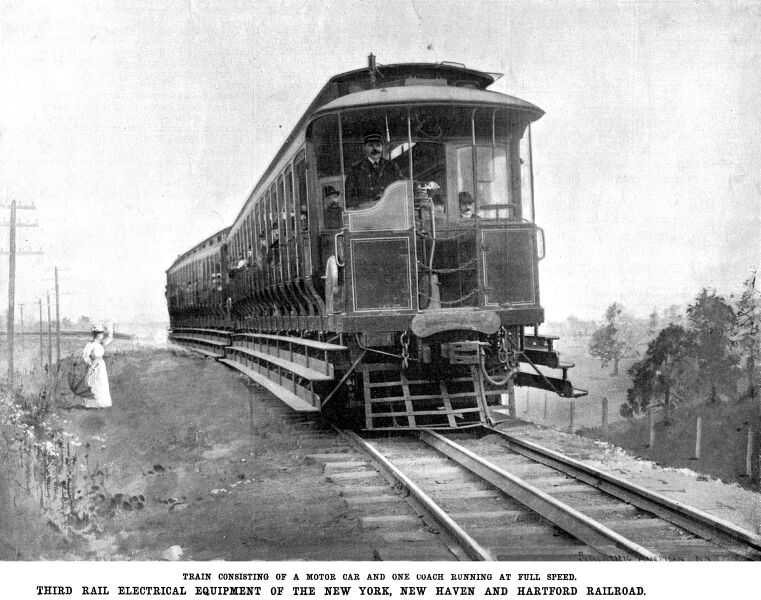
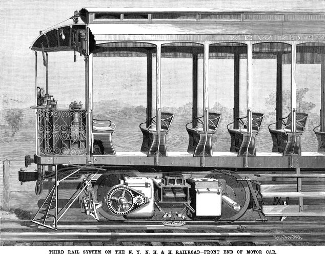
The general appearance and mechanical details of the open cars
are shown very clearly in our front page and other illustrations.
They are 51 feet long, and are provided with sixteen seats, each
of which can accommodate six passengers, the capacity of a two-car
train being, therefore, 192 passengers. The current is taken from
the third rail by means of a sliding contact shoe, which consists
of a simple cast iron plate 5 inches wide by 12 inches long, weighing
about 12 pounds. It is carried by an insulated support, to which
it is fastened by jointed links, which allow it to bear upon the
rail at all times with a pressure due to its own weight. Each
train is made up of a motor car and a trailer. Each motor car
has two 125 horse power motors, both of which are mounted upon
one track, as shown in the accompanying engraving, in which the
casing has been removed to show the gearing of the forward motor.
It can well be understood that in a service of this kind, where
the high speeds which are customary in the steam service are to
be regularly made, special attention had to be given to the question
of braking. As hand-operated brakes were out of the question and
steam was not available, it was determined to equip the motor
cars with a separate electrically driven air brake plant. The
details of this successful and highly creditable work are shown
in the upper front page engraving and its position on the front
platform is shown in the side view of the car.
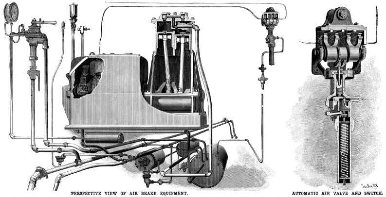
The two cylinder, single acting compressor is driven by a direct
connected 10 horse power motor. The compressor has a capacity
of 52½ cubic feet of air per minute under a gage pressure
of 90 pounds per square inch. The speed is 250 revolutions per
minute and the consumption 16 amperes at 600 volts. The standard
Westinghouse air brake equipment of the company is used on the
cars, and it is controlled by the usual engineer's valve, as shown
in the engraving. One of the most ingenious features is the automatic
valve and switch for starting and stopping the compressor, of
which a sectional view will be found on the front page. By reference
to the engraving it will be seen that air is led in above a small
piston, which works in a vertical cylinder and is pressed upward
by a coil spring. The spring is set at the working pressure of
90 pounds to the square inch. As soon as the air pressure exceeds
90 pounds, the piston is forced down, carrying with it a small
vertical valve stem and allowing the air to pass up into a small
Cylinder located beneath the electrical switch which controls
the motor of the air compressors. Here it pushes up a piston which
throws over the electrical contacts and opens the switch. As the
air pressure falls it releases the lower piston, which rises to
its normal position. As it rises, a catch on the piston rod lifts
the small lever shown to the left and opens a release valve below
the switch cylinder above mentioned. The upper piston now falls
and closes the switch, thereby starting the motor of the air compressor.
The device has given complete satisfaction. It may be set to work
at from 45 to 100 pounds pressure, and on a variation of from
5 to 7 pounds pressure.
 The air compressor
is placed, as shown, on the front platform of the car to the left
of the motorman. In front of the compressor is the wheel of the
hand brake, and conveniently arranged in front of the motorman
are the pressure gage, the engineer's air valve and the controller.
The lever for operating the air chime whistle passes through the
hood just above the motorman's head. Beneath the hood on the front
of the car above the door are the current breaker and the main
switch. On the front rail of the platform there is also a conductor's
signal whistle. The air compressor
is placed, as shown, on the front platform of the car to the left
of the motorman. In front of the compressor is the wheel of the
hand brake, and conveniently arranged in front of the motorman
are the pressure gage, the engineer's air valve and the controller.
The lever for operating the air chime whistle passes through the
hood just above the motorman's head. Beneath the hood on the front
of the car above the door are the current breaker and the main
switch. On the front rail of the platform there is also a conductor's
signal whistle.
The current passes from the shoes through flexible copper cables
to the circuit breakers. After passing through these it is led
through a lightning arrester and a "kicking coil." It
then divides, passing to the controllers on each platform. At
each controller it passes through a magnetic blow-out coil, and
is led by cable to the resistance situated in the center of the
car. It then returns through the resistance contacts to the controller
cylinder and the motors.
The danger to the public from the use of the third rail is
considerably less than is popularly supposed, and in view of the
precautions which have been taken to safeguard the ignorant or
unwary, the chance of accident is very small. At the Berlin and
Hartford stations the third rail section is fenced in on both
sides. At New Britain, where the two lines converge, a switchman's
tower has been built in the Y
where the roads converge. Underground cables connect the rail
where it enters the station with a switchboard in the tower. When
a train has stopped in the station the third rail is cut out,
and it is not thrown in until the train is ready to start again.
When the road which has now been electrically equipped was
operated by steam, eight trains a day were run each way between
Hartford and New Britain, and fourteen trains a day between New
Britain and Berlin. Under the present system of two-car trains
will be run every half hour between Hartford and New Britain from
six in the morning till twelve at night. The run of 9.3 miles
will be made in something under twenty minutes, and the fare will
be ten cents each way. Sixteen trains a day will be run between
New Britain and Berlin, a distance of three miles, the fare being
five cents for a single trip.
We reserve further particulars and illustrations of this interesting
plant for a later issue.
Electric Article 2 | Lines
West | Stories Page | Contents
Page
This page originally appeared on Thomas Ehrenreich's Railroad Extra Website
|


