EARLY RAILS, SILLS, A STONE BLOCKS.
DETAILED DESCRIPTIONS OF THE METHODS USED ON THE
PHILADELPHIA AND COLUMBIA RAILROAD
The exact nature and cost of the methods adopted on the Philadelphia
and Columbia Railroad are shown by the following data extracted
from a note-book in which Mr. W. Hasell Wilson commenced writing,
in 1831, such information as he considered valuable, while he
was acting as principal assistant engineer on that road, under
the direction of his father, Major John Wilson, chief engineer:—
Description and Estimate of Granite Railway,
as Laid on the
Columbia and Philadelphia Railway.
SILLS.—The sills are in lengths of not less than
three feet; the size, one foot square, or containing not less
than a square foot in the cross section, none, however, being
less than eight inches in depth; the shape as nearly square as
possible; the bed and upper surface, particularly, ought to be
parallel. The upper surface is dressed for about five or six inches,
to afford a smooth bearing for the iron. That part of the sill
outside of the iron is reduced to the same level, but not so smoothly.
The ends of the sills are dressed square, so as to be in contact
for at least three inches in depth below the iron, and for six
inches across the stone, exclusive of the chamfering.
BROKEN STONE.—The broken stone, the particles of
which must not be larger than it cube of two inches, are to be
kept clear from earth, clay, or other material.
TRENCHES.—The trenches are not less than two feet
in width, and twenty-two inches in depth, below the top of the
sill, except where the stone sill is wider than one foot, and
where rock occurs in the trench. In the former case, the trench
is made of such width as to admit of four inches of broken stone
on each side of the sill; in the latter, the depth will be such
as to allow four inches of broken stone under the sill.
LAYING.—The broken stone are placed in layers of
three inches, each layer well compacted with a heavy rammer. The
sills are then laid, and bedded with a heavy rammer.
The Holes are then drilled to correspond with the holes on
the bars, and to suit the width and position of the track, not
less than three and a half inches in depth, and five-eighths in
diameter. No hole is drilled within three inches of the end of
a sill. The plugs are of seasoned locust, fitting the hole exactly,
but not requiring much driving. The bar is then spiked on, and
the inner edge of the sill chamfered off, in width two inches,
and in depth one inch and a half.
THE HORSE PATH is filled in, and the earth sloped from the
back of the sills, to turn off the water collecting on the surface.
THE IRON BARS are in lengths of fifteen feet, two and a quarter
inches in width, and five-eighths of an inch in thickness. The
spikes are three and a half inches in length, and three-eighths
of an inch square, the heads fitting the countersink of the bar.
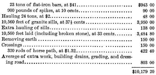
Estimate for One Mile of the Granite Railway, as Completed
by Robinson, Carr & Co.
Description and Estimate of a Wooden Railway.
SILLS.—The sills are chestnut, white oak, or chestnut
oak, seven and a half feet in length, and of such size as to square
seven inches, dressed flat on the under side, and notched on the
tipper.
TRENCHES.—The trenches are four feet apart, from centre
to centre, one foot in width, sixteen in depth (making twenty-four
inches to top of wooden rail), and eight feet in length.
RAIL.—The wooden rail is yellow pine, six inches square.
The keys are of white oak or yellow pine, one foot in length,
two inches in height, and one inch and a half thick, tapering
to three-quarters.
In notching the sills for the rail, there must be left at least
three inches of a bearing under the rail.
Estimate for One Mile of Wooden Railway as Completed
Edge Rails on Stone Blocks and Stone Sills, as
Laid Between Broad Street and Schuylkill River.
BLOCKS.—The blocks are of granite, twenty inches in length,
sixteen in width, and twelve in depth; depth of holes, six inches;
diameter, one inch.
SILLS.—The transverse sills are of granite, six and a
half feet in length, and twelve inches square. These are placed
it the joining of the bars, about fifteen feet front centre to
centre.
TRENCHES.—The trenches are twenty-eight inches wide, and
twenty-four inches deep (from the top of the block).
LAYING.—The broken stone are placed in layers of three
inches, well rammed; the blocks and sills then laid, three feet
apart from centre to centre. They are then drilled, the chairs
fastened on, and the iron bars laid and keyed. The broken stone
are now rammed around the blocks and sills, and the horse path
filled in.
THE IRON is the same as that used on the Wigan railway, the
rail weighing forty-one and a quarter pounds to the yard. Between
the chair and block a piece of canvas is inserted (the size of
the chair), soaked in tar.
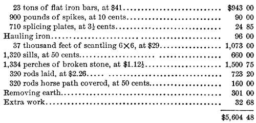
Estimate for One Mile of Edge Rails on Stone Blocks and
Sills, as Completed.
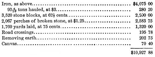
Estimate for One Mile, Without Stone Sills, as Laid.
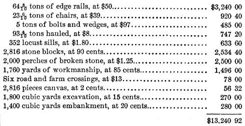
Description and Estimate of Edge Rails on Stone Blocks
and Locust Sills, as Laid Between Columbia and the Intersection
of the West Chester Railway.
BLOCKS.—Granite, limestone, or sandstone, 22in. x 16 in.
x 12in.
SILLS.—Locust 7½ feet long, 6 x 8 inches, laid
15 feet apart, and on the flat side; in the curves they are placed
9 feet apart. The rails are not joined on the sills, but on the
nearest blocks, but not opposite. A cross trench is dug for each
sill, and filled with broken stone, which, on the embankments,
is continued out to the edge of the bank, thereby serving as a
drain. Between the rails, the space is filled up with earth to
a level with the top of the blocks. The holes in the blocks are
drilled six inches in depth, and one and a half inches in diameter,
then plugged with red cedar, which is previously bored through
the centre, half an inch in diameter, the bolt being five-eighths.
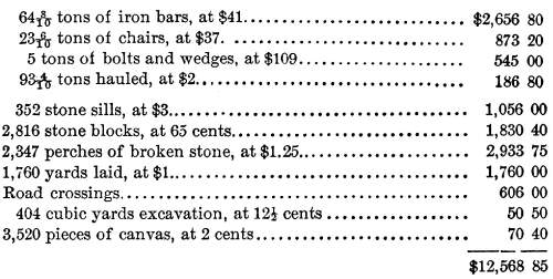
Estimate for One Mile of Edge Rails on Stone Blocks
and Locust Sills; Prices Averaged from Contracts Completed.
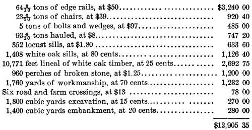
Description and Estimate of Edge Rails on Wooden
Cross Sills and Bearing Timbers.
THE BEARING TIMBERS are white oak, 10 x 12 inches, and in lengths
of not less than 20 feet, laid edgewise, and notched down two
inches, every three feet, to receive the cross sills.
At the joinings of these timbers, there is a tenon 4 inches
thick, and the whole width of the timber, laying horizontally
across the centre of the stick, and projecting six inches with
a mortice (to fit) on the opposite stick, secured by a wooden
pin. The sills are 7½ feet long, 6 x 8 inches, of white
oak, or chestnut, except at intervals of 15 feet on the straight
lines and 9 feet oil the curves, where they are of locust. They
are laid on the flat side, and secured to the bearing timbers
by wooden keys.
Estimate for One Mile of Edge Rails Upon Bearing Timbers
and Sills, with Locust Sills at Every Fifteen Feet.
It will be seen that the estimates given above relate to six
styles or variations in construction. The word sills is sometimes
used to indicate wood or stone which performed functions similar
to those now entrusted to ties, especially when they are called
cross sills, and sometimes to indicate a continuous foundation
on which rails were laid; and the relatively small number of cross
sills (or ties) used, indicates that at the Outset the danger
of the tracks spreading was not fully realized. It is somewhat
surprising, too, to note how nearly one of the systems adopted
approximated to modem methods in the matter of creating a foundation
of broken stone, and using wooden cross sills or ties.
"SNAKE HEADS."
A large proportion of the early railway tracks represented
close imitations of a style adopted by early coal roads, consisting
of bars of iron spiked on stringers of wood, and this style was
so extensively employed, and continued in use in some sections
for such a protracted period, that "snake heads" became
one of the recognized and most important of early railway perils.
This term was suggested by the liability of the iron bar to become
loosened from its fastenings as a train moved over it, and it
would sometimes suddenly turn upward with sufficient force to
pierce the bottom of cars, and occasionally injure passengers,
or throw a train from the track. As it was not until near the
middle of the fifth decade of the nineteenth century that iron
rails were manufactured in this country, except a few cast-iron
rails and flat bars, it was necessary to import all rolled-iron
rails that were used here, and this operation, together with the
large amount of iron required even by the edge rails then used,
necessitated a greater expenditure than could be afforded by many
of the earlier companies.
Horatio Allen, chief engineer of the South Carolina Railroad,
which had 10 miles in operation in 1830, and increased this mileage
by 52 miles in 1832, and 75 miles in 1833, and which for a time
enjoyed the distinction of being the longest continuous railway
in the United States, and the first to use a locomotive of American
construction, says of this road, that "it was of the age
of wooden rails capped with iron. Confidence and capital had not
yet reached the growth to make an iron track of the most modest
weight per yard a possibility, and steel rails were as unthought
of as the telegraph. On timber rails, 6inch X12-inch section,
iron bars 21-ineb x ½-inch were spiked. The wood was the
southern pine, the bard, resinous surface of which was as suitable
for the iron bars as wood could be."
The South Carolina was one of the first companies to substitute
edge or iron rails for iron bars or plates over its entire line,
as this course was adopted a few years after the completion of
the road. The desire of engineers and managers to secure such
an advance was very general, as they fully appreciated its importance,
and explained the advantages derived from its use in the way of
saving operating expenses, but the difference in cost of construction,
when comparatively heavy edge rails were used, was at one time
estimated at about $6,000 per mile, and this outlay was too great
to be borne by most of the early companies. The result was that
flat bars continued to furnish the iron for many tracks during
a protracted period. In 1839 all the New York railways, except
the Long Island, used flat bars. All the railways in Pennsylvania
used iron plates or bars, varying in dimensions from 1½
x three-eighths, on short early mine roads, to 2¼ x five-eighths,
except the state railways; the Norristown line, which at that
time used 40-pound rail; the Philadelphia and Reading, which used
45-pound rail; the York and Wrightsville; Buck Mountain; Little
Schuylkill and Susquehanna; Beaver Meadow extension; and West
Branch, a road leading from Schuylkill Haven to Mine Hill. All
the railways of Virginia, North and South Carolina, Georgia, and
Florida used flat bars, varying in dimensions from 2 x ½
to 2½ x ¾ except the South Carolina, and portions
of the Georgia and Central roads, of Georgia. All the railways
of Alabama, Louisiana, Mississippi, Tennessee, and Kentucky used
flat bars, except the Pontchartrain, of New Orleans; the Mississippi;
the Vicksburg and Jackson, and the Grand Gulf and Port Gibson.
All the railways of the Western states used iron bars or plates
except the Madison and Indianapolis.
WOODEN "RAILS," STRING PIECES, OR STRINGERS.
In a large proportion of the very early railroads wood was
extensively used of such shapes and patterns that, in the railway
language of that day, it was generally called "rails."
Some of the primitive lines did not even have these wooden rails
covered with flat iron bars, and they were called wooden rail-roads,
a term which was also frequently applied to the forms of construction
in which the wooden rail was plated with iron bars. Timber rails
were an article of commerce. Considerable quantities were sent
from South Carolina and North Carolina to be used on the early
railways in Pennsylvania. Their dimensions were sometimes 5 x
9; and sometimes 5 inches wide and 7 deep, and they were usually
plated with flat iron bars. The dimensions of these bars was frequently
a matter of considerable importance. When the bars were narrow
and thin it was found that under the pressure of heavy loads,
the bars would bend and sink into the wooden rail. To obviate
this effect, a small sheet of zinc was sometimes placed beneath
the ends of the iron rails. The wooden rails, string pieces, or
stringers, rested frequently on wooden ties which were then called
sleepers.
The following description of an early road of a class which,
while it did not represent the highest rank, was very much better
than a number of inferior roads, was published in 1832, in the
notes appended to Mr. G. W. Smith's American edition of Wood's
Treatise on Railroads. The account was furnished by Messrs. Kughler
and Dundas:—
"The Mine Hill and Schuylkill Haven Railroad was begun in
June, 1829, and finished, the main line, in June, 1830, and the
remainder in June, 1831. The main line commences at Schuylkill
Haven, and extends 101 miles along the west branch of the river
Schuylkill, through the Mine Hill Gap. At the fork of this branch
with the west-west branch of the river, 6 miles from Schuylkill
Haven, a branch of the railroad extends along the last-mentioned
arm of the river, 3½ miles of a double track, and one mile
of a single track, but graded for a double track, making 14 miles
of a double track, and one of a single, or 15 miles in the whole.
The company have disbursed for all expenses, in completing this
work, $181,165. The width of the track is 4 feet 8½ inches.
The sleepers (white oak) are 4 feet apart, from centre
to centre, and average 10 x 8 inches. The wooden rails (white
oak) are 4 x 7 inches. The iron rails are 1½ inches wide
by half an inch thick. The curves are in no instance of a radius
less than 400 feet, but generally 500 feet. The grades do not
exceed 30 feet to the mile, except on two inclined planes, the
first of which is 80 feet to the mile; the second 150 feet to
the mile. The sleepers rest on stone rubble work, in three parallel
lines, from one end of the road to the other. There are 50 bridges,
each of 28-feet span. The highest embankment is 21 feet, and the
deepest excavation 31 feet. There are 12 culverts, and several
minor bridges and drains.
COST.
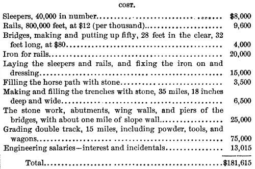
This is as near the actual cost as can be obtained."
It will be perceived that in this statement the wood on which
the iron rested was designated "rails," while the iron
with which they were plated was described as "iron for rails."
ORIGIN OF THE T-RAIL.
The imperfections of the snake-head rails and of the early
English substitutes for them suggested to an American, Mr. Robert
L. Stevens, of Hoboken, who was the son of Col. John Stevens,
the prominent early American advocate of railways, an improvement
in rail construction which is the progenitor of the present T-rail.
It is stated that when Mr. Robert L. Stevens, who was actively
identified with the construction of the Camden and Amboy Railroad,
"was on the ship, on his way to Europe to order the 'John
Bull,' in 1830, he devoted a considerable amount of time to whittling
out cross-sections of what be thought Would be a good kind of
iron rails to lay on the railroad. The best rail then known was
the T-rail without any base.
This style had been adopted by all the most important roads in
Europe. Owing to its peculiar shape, it required a chair on every
cross-tie or stone block, as the case might be. Stevens was the
first man to design the rail which he termed the H-rail—in
other words, a rail with a base which could be spiked with 'hook-headed'
spikes directly to the bearing." Rails made in accordance
with this pattern were laid down upon the Camden and Amboy when
it was first constructed, and methods were also adopted for joining
or splicing the rails which represent a great advance on the systems
then generally prevailing. Of these rails a report of the company
says that they were of the I form invented by Mr. Stevens,
3½ inches high, 2½ inches on the upper running surface,
and 3½ inches in width on its base, weighing 42 pounds
to the yard.
The writer has been credibly informed that Mr. Stevens encountered
great difficulty in his efforts to induce a British rail mill
to make rails of the improved pattern he had devised. He was obliged
to assume the whole responsibility of the scheme, to pay all the
extra expenses, and to give heavy security to guard the works
against all description of damages that could possibly be inflicted
on the rail Works by this innovation, which was evidently regarded
as dangerous, or at least highly imprudent, and likely to prove
disastrous to all concorned. The supposed grounds for such adverse
views must have made a deep impression, for it long period elapsed
before the use of T-rails became
approximately universal, although some companies adopted the T-rail a few years after it was first
used on the Camden and Amboy. The T-rail
became widely known as the Vignoles rail, rather than the Stevens
rail, because a European engineer, Mr. C. B. Vignoles, hastened
its introduction on European railways, using them on English roads
during the progress of construction to an extent that gave to
them the title of contractors' rails.
A recognition of the usefulness of the improvement must have
been comparatively rapid, because by or before 1840 the H- or T-rail
was in use on all or portions of the following American lines,
viz.: Camden and Amboy; Philadelphia and Reading; Philadelphia,
Wilmington and Baltimore; Long Island; portions of the Philadelphia
and Columbia Railroad, on which flat, plate, or bar-iron rails
had originally been laid; on important New England roads, including
the second track of the Boston and Lowell, Boston and Worcester,
Boston and Providence, Providence and Stonington; New Castle and
Frenchtown; Washington branch of the Baltimore and Ohio, and portions
of the Georgia Railroad.
In a description of the Camden and Amboy Railroad, contained
in Mr. George W. Smith's appendix to Wood's Treatise on Railroads,
and published in 1832, the following reference is made to the
T- or H-rails
used: "The rails are of rolled iron, 16 feet long, 2-one-eighth
inches wide on the top, 3¼ inches at the bottom and 3½
deep; the Dock half-inch thick. The weight is 209 pounds = 39-three-sixteenths
pounds per yard. They are secured by clamps of iron, riveted at
the extremity of each bar. The rails are attached to the stone
blocks and sleepers by means of nails or pins at the sides, driven
into wooden plugs. Chairs are dispensed with."
The following interesting letter relating to this subject is
published in Mr. J. M. Swank's census report of 1880, on iron
and steel manufactures, the writer of the letter being a nephew
of Mr. Robert L. Stevens:—
"HOBOKEN, NEW JERSEY, May 31, 1881.
DEAR SIR: In answer to your letter of the 27th instant 1 will
say that I have always believed that Robert L. Stevens was the
inventor of what is called the T-rail,
and also of the method of fastening it by spikes, and I have never
known his right to the invention questioned.
The rail of the Liverpool and Manchester Railroad, on its opening,
in September, 1830, was of wrought iron, divided into fish-bellied
sections, each section being supported by a cast-iron chair, to
which it was secured by a wooden wedge. The form was derived from
the old cast-iron fish-bellied train rail, cast in single sections,
each about 36 inches long. This wrought-iron rail was afterwards
improved by making its bottom straight uniformly throughout its
length.
Mr. Stevens' invention consisted in adding the broad flange
on the bottom, with a base sufficient to carry the load, and shaped
so that it could be secured to the wood below it by spikes with
hooked heads; thus dispensing with the cast-iron chair, and making
the rail and its fastenings such as it now is in common use. In
the year 1836 and frequently afterwards he spoke to me about his
invention of this rail, and told me that in London, after unsuccessful
applications elsewhere in England, shortly after the opening of
the Liverpool and Manchester Railroad, he had applied to Mr. Guest,
a member of Parliament, who had large rolling mills in Wales,
to take a contract to make his rail for the Camden and Amboy Railroad,
of which he was the chief engineer; that Mr. Guest wished to take
the contract, but considered that it would be impracticable to
roll the rail straight; that, finally, Mr. Guest agreed to go
to Wales with him and make a trial; that great difficulty was
at first experienced, as the rails coming from the rolls curled
like snakes, and distorted in every imaginable way; that, by perseverance,
the rail was finally successfully rolled; and that Mr. Guest took
the contract. The Camden and Amboy Railroad, laid with this rail,
was opened October 9th, 1832, two years after the opening of the
Liverpool and Manchester Railroad. Of this I was a witness.
This rail, long known as the old Camden and Amboy rail, differed
but little, either in shape or proportions, from the T-rail now in common use, but weighed
only 36 pounds to the yard. For the next six or eight years after
the opening of the Camden and Amboy Railroad this rail was but
little used here or abroad, nearly all the roads built in the
United States using the flat iron bar, about 2½ inches
by ¾ inch, nailed to wooden rails, and the English continuing
to use the chair and wedge.
My uncle always regretted that he had not patented his invention.
He mentioned to me, upwards of forty years ago, that when advised
by his friend, Mr. F. B. Ogden, the American consul at Liverpool,
who was familiar with the circumstances of his invention, to patent
it, he found that it was too late, and that his invention had
become public property.
Yours, truly,
FRANCIS B. STEVENS."
DIVERSITIES IN PERMANENT WAY.
In addition to the plans of construction heretofore referred
to, various modifications were adopted in different localities,
the most important of which were rendered possible by the T-or H-rail.
The Boston and Lowell used, in its first track, edge rails which
were not parallel, but of the fish-bellied pattern, i.e.,
their bottoms were slightly curved, as the body of a fish is curved,
so that the amount of iron used was greatest at the points most
distant from the rail joints. Where the H-
or T-rail was used numerous chairs
ceased to be indispensable, as this rail, unlike the edge rail,
was self-supporting, and the use of chairs was generally confined
to places where the rails were united. A greater number of sleepers
or ties than had originally been considered desirable were put
down in the tracks of some roads. On the Boston and Providence
sleepers of white cedar were laid down 3 feet apart from centre
to centre. They were seven feet long and six inches thick, and
rested on broader sills of hemlock. On the Philadelphia and Reading,
on which H-rails, weighing 45-one-eighth
pounds per yard were used, the rails were laid upon white oak
sleepers, or cross-ties, seven feet in length, and of a uniform
depth or thickness of seven inches. They were laid 3½ feet
apart from centre to centre, and each sleeper was laid upon a
prism of broken stone, deposited in a trench 14 inches deep, 12
inches wide, and 9 feet long across the line of the track. At
the rail joints the rails rested upon cast-iron chairs, let into
the sleepers by means of notches cut for that purpose. The chair
was six inches square at its lower surface, where it was five-eighths
of an inch in thickness. There were bolts, with nut screws attached,
to hold the ends of the two rails to the chair. The bolt and nut
weighed 7 ounces, and the chair 10½ pounds. The chairs,
and the rails, at the points where they rested on sleepers, were
spiked down, with spikes six inches in length, with stems three-fourths
by five-eighths of an inch. In a mile of track of the Philadelphia
and Reading, built in accordance with these requirements, there
were 563 bars of iron, weighing 71 tons; 563 chairs, weighing
5,910 pounds; 7,882 spikes, weighing 4,524 pounds; 1,126 screw
bolts and nuts, weighing 481 pounds, and 1,689 sleepers. The entire
cost of the single track as laid, was reported to be $7,617 per
mile. As the road was intended, from the outset, for exceptionally
heavy traffic, it was much more substantially built, in every
respect, than was usual at the time of its construction, and the
rails proved to be very serviceable.
On portions of the Western (of Massachusetts), which were being
constructed about 1840, a mode was adopted which differs in some
important respects from any of those heretofore described. The
rails were of the U or bridge
pattern. A contemporaneous description says: "The rails are
of wrought iron, rolled in lengths of fifteen feet, and made hollow.
The top is two inches wide, base six inches, and height one inch
and three-quarters. Holes are punctured in the flanges on both
sides, about eighteen inches apart, to secure the rail (without
chairs) to the sleepers, by means of screws eight inches long.
To prevent the sleepers from spreading, there are, at every fifteen
feet, iron ties across the railway, spiked down at each end of
the sleepers."
In this description the term sleepers was used to designate
"longitudinal, continuous sleepers of Memal timber kyanized,
thirteen or fourteen inches wide, by six and a half or seven inches
thick, which are firmly bedded on the ground, previously made
even and well rammed. On the top of the sleepers are laid the
rails." Another feature was an effort to give the outer edge
of the rail a slightly higher altitude than the inner edge, for
the purpose of making the surface of the rail correspond as closely
as possible with the conical shape of the car wheels. Other railways
endeavored to accomplish that object at comparatively early periods,
but the results were usually not satisfactory.
Transport Systems
| Antebellum RR | Contents
Page
|


