The Evolution of the American
Locomotive.
Scientific American Supplement—May
8, 1897 (Part 3 of 3)
By HERBERT T. WALKER.
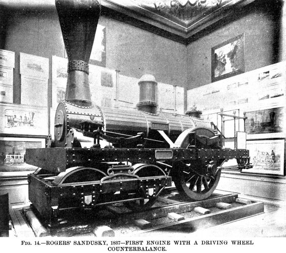 FIG. 14
illustrates the Sandusky, the first locomotive built at the famous
Rogers Locomotive Works, Paterson, N. J. At that time the name
of the firm was Rogers, Ketchum & Grosvenor, and its founder
Thomas Rogers, designed this engine. The late Zerah Colburn remarked
that "Thomas Rogers maybe fairly said to have done more for
the modern American locomotive than any of his contemporaries." FIG. 14
illustrates the Sandusky, the first locomotive built at the famous
Rogers Locomotive Works, Paterson, N. J. At that time the name
of the firm was Rogers, Ketchum & Grosvenor, and its founder
Thomas Rogers, designed this engine. The late Zerah Colburn remarked
that "Thomas Rogers maybe fairly said to have done more for
the modern American locomotive than any of his contemporaries."
The Sandusky ran its trial trip from Paterson to Jersey City
and New Brunswick and back October 6, 1837, its performance being
entirely satisfactory. It was intended for the New Jersey Railroad
and Transportation Company, but was, however, bought for the Mad
River and Lake Erie Railroad by its president, Mr. J. H. James,
of Urbana, O. It continued in service many years. The cylinders
were 11 in. in diameter by 16 in. stroke. Driving wheels 4 ft.
6 in. diameter; truck wheels 2 ft. 6 in. diameter. The general
design did not differ materially from the Experiment (Fig 11),
but it is of interest as being the first locomotive with weights
on the driving wheels to counterbalance the cranks and connecting
rods. For this Mr. Rogers filed a specification in the Patent
Office dated July 12,1837, in which he says, "The irregular
motion which arises from not having the cranks and connecting
rods balanced is attended with much injury to the engine and to
the road, and with much loss of power." The driving wheels
were of cast iron, with hollow spokes and rims, which at that
time was a remarkable novelty. The section of the spokes was of
oval form, and the rim of very much the same shape as that which
is in common use to-day. In order to counterbalance the parts
referred to, the rim of the wheel opposite the crank was cast
solid. The importance of counterbalancing was not recognized until
several years after it had been introduced by Mr. Rogers, but
to-day it would be hard to find a locomotive without counterbalanced
driving wheels.
Another sporadic form of locomotive engine was built by Gillingham
& Winans, of Baltimore, for the Baltimore and Ohio Railroad,
in the year 1838. They had upright boilers, but the cylinders
were horizontal and were connected to cranks on an intermediate
shaft, which was geared to a second shaft having outside cranks
to which the four driving wheels were coupled. These engines were
of ungainly form and were nicknamed "crabs," but in
the year 1844 Mr. Winans brought out another class of engine retaining
substantially the same system of gearing but with eight coupled
wheels instead of four, and a horizontal boiler. These engines
were ignominiously named "mud diggers," but they did
heavy freight service on the Baltimore and Ohio Railroad for many
years.
At this period it will be necessary to revisit England to see
what was going on in the shops of Robert Stephenson & Company,
Newcastle upon Tyne, in 1842. In that year it appears that the
link motion was reinvented without previous knowledge of James’
invention. William Howe, a mechanic employed in Stephenson’s
shops, decided to place a curved link between the eccentric rods
to take the place of the Stephenson "fork motion," then
in general use. He made a pencil sketch and wooden model which
were shown to Robert Stephenson, who, seeing its merits, ordered
it to be fitted to all engines constructed at his works, and from
that time it has been known as "Stephenson’s link motion."
The first engine equipped with this gear was No. 71, for the North
Midland Railway, and commenced to run September 10, 1842. There
was a dispute between Howe and an apprentice named Williams, who
claimed to have a share in the invention, but as we have not space
to enter into the details of the controversy, the reader is referred
to Colburn’s "Locomotive Engineering," where the
matter is very ably dealt with.
But not even when the link was being used with such remarkable
success in England did American engineers recognize its merits,
and it was not until 1847 that it was adopted in this country.
In the year 1849 Mr. Thomas Rogers introduced it in his practice,
fitting a stationary link motion to some engines for the Hudson
River Railroad. In this arrangement the curve of the link was
convex toward the eccentrics, instead of concave, as in the Stephenson
gear, and the link was suspended on a fixed center, the valve
rod block being moved up and down instead of the link. This plan
was introduced by Sir Daniel Gooch, master mechanic of the Great
Western Railway, of England, about the year 1845. In 1850 Mr.
Rogers commenced to build engines with the shifting link motion,
and soon afterward it came into general use. Other builders, however,
strenuously resisted the innovation, and none more so than Mr.
Baldwin, who could not be induced to adopt it until the year 1854,
when he fitted the link to the Pennsylvania, an engine for the
Central Railroad of Georgia.
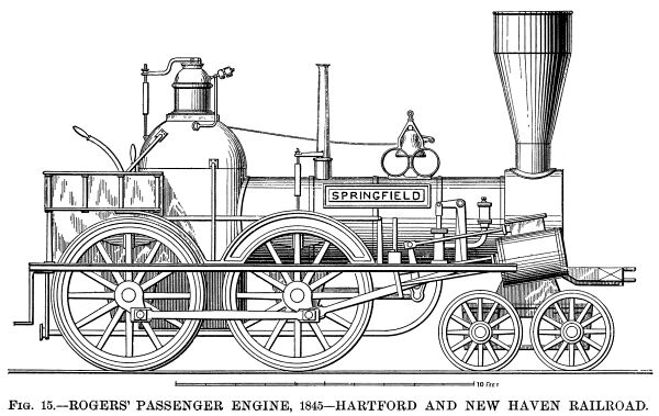 The next example
of progress in locomotive construction is illustrated in Fig.
15, which shows a very good engine designed by Mr. Rogers
and built at his works, in 1845, for the Hartford and New Haven
Railroad. It had equalizing levers between the driving wheel springs,
which do not show in the drawing. The truck had side bearings
and springs on the sides of truck. The pumps had short stroke
and were worked from the crosshead as shown. The cylinders were
11½ in. diameter by 18 in. stroke. Driving wheels 5 ft.
diameter. We notice the supplemental frame that supports the running
board. It illustrates the transition from outside to inside framing.
The frames were of bar iron and the reversing gear was the hook
or fork motion. The next example
of progress in locomotive construction is illustrated in Fig.
15, which shows a very good engine designed by Mr. Rogers
and built at his works, in 1845, for the Hartford and New Haven
Railroad. It had equalizing levers between the driving wheel springs,
which do not show in the drawing. The truck had side bearings
and springs on the sides of truck. The pumps had short stroke
and were worked from the crosshead as shown. The cylinders were
11½ in. diameter by 18 in. stroke. Driving wheels 5 ft.
diameter. We notice the supplemental frame that supports the running
board. It illustrates the transition from outside to inside framing.
The frames were of bar iron and the reversing gear was the hook
or fork motion.
The writer has not succeeded in discovering when the first
sand boxes were used. The early locomotives were without them.
When the engine slipped, the fireman jumped down and threw some
gravel on the rails with his shovel, or, failing that, he used
the pinchbar, with verbal encouragements, more powerful than polite,
from the engine driver. The next step appears to have been a bucket
of sand carried on the foot board, and scattered by hand when
required. Mr. Baldwin commenced to place sand boxes on his engines
in the year 1846 for the Philadelphia and Reading Railroad. The
chief objection to sand is that, while it prevents the driving
wheels from slipping, it has a retarding effect on the train wheels,
which, with a heavy load on a hill, is a very serious drawback.
To overcome this, a jet of steam or water has been tried, and
with a measure of success, as it is well known that thoroghly
wet rails will give almost as good adhesion as when they are perfectly
dry. An electric current has been passed through the driving wheels
and rails to prevent slipping; but none of these devices are equal
to good dry sand.
In the year 1846, Septimus Norris, a brother of William Norris,
patented a ten wheel freight engine with six driving wheels combined
with a leading truck. Several of these were built for the Philadelphia
and Reading Railroad.
An interesting locomotive is illustrated by Fig. 16,
which shows one of a class built at the Norris Works about the
year 1847, for the Camden and Amboy Railroad. There were several
of these engines built, most of them having driving wheels 8 ft.
in diameter and cylinders variously 13 in. by 34 in., 13 in. by
38 in. and 14 in. by 38 in. stroke. Their weight was about 22
tons in working trim. This type of engine has the driving wheels
behind the firebox and is known as the "Crampton" class,
having been patented in 1843 by the late Thomas Russell Crampton,
an English engineer of some distinction. He did not, however,
originate the idea, as Baldwin built engines with the driving
wheels behind the firebox in the year 1833. The advocates of this
class of engine claimed that it admitted of driving wheels of
practically unlimited diameter, while the boiler could be dropped
down to the axles of the carrying wheels, thus enabling an engine
with large driving wheels to have a low center of gravity, which
was at that time and for years afterward considered necessary
for safety at high speeds. Crampton engines never came into general
use anywhere except in France, where the "système
Crampton" was very popular and it is believed that some of
the engines are still running.
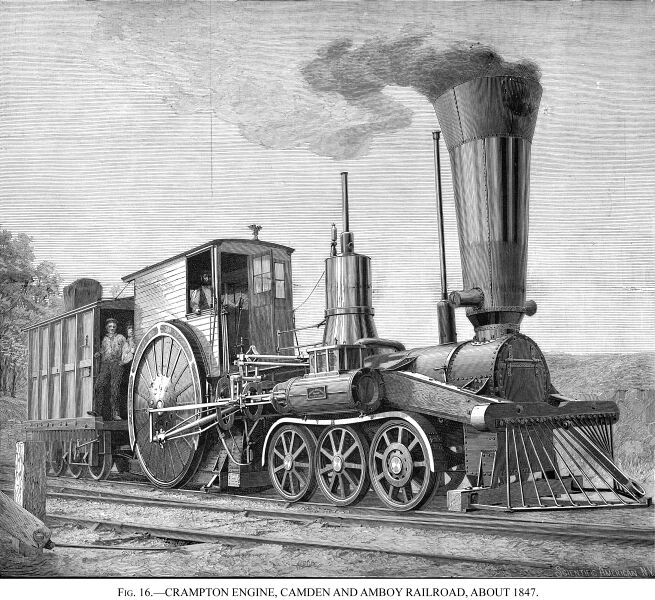
Referring to the example before us (Fig. 16), we are
informed that these engines made steam slowly, which was probably
caused by the fact that the boilers were small compared with the
immense cylinders and driving wheels. Another drawback to them
was that they lacked adhesive weight, having only about 8 tons
on the driving wheels; it was, therefore, hard to start them with
a train, although when under headway they occasionally covered
a mile in 53 seconds. But the most serious objection to there
was their tendency to run off the track when traveling fast, the
chief reason being that the propelling mechanism at the rear end,
with unbalanced driving wheels, caused the front end to "nose"
or oscillate laterally. It will be observed that the driving wheels
had a wood filling between the spokes to prevent "raising
dust."
Fig. 17 illustrates a fine engine designed by Mr. McQueen
for the Hudson River Railroad (now apart of the New York Central
and Hudson River Railroad). It is interesting not only for the
excellence of the design, but because it was one of the first
engines to do regular everyday express work on the road that now
claims to have the fastest regular train in the world. It appears
that the Hudson River steamboats, even as far back as 1845, offered
great inducements to travelers by reason of their luxurious accommodation
and high speeds, and these express trains were put on to compete
with them. A writer in the Practical 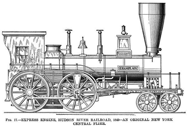 Mechanic’s Journal of 1850-51, in describing this
engine, said: "The usual speed of railroads was not so much
greater as to induce the passengers to leave the magnificent floating
palaces. Great speed must, therefore, be determined on."
The result was the Champlain, which commenced working the express
trains between Thirty-first Street, New York, and Poughkeepsie,
72 miles, in December, 1849. The distance was covered in 2 hours
25 minutes = 29.79 miles an hour, including twelve stops. The
weight of the trains averaged 94 tons, exclusive of engine and
tender. The ordinary trains did the same distance in 2 hours 45
minutes. Mechanic’s Journal of 1850-51, in describing this
engine, said: "The usual speed of railroads was not so much
greater as to induce the passengers to leave the magnificent floating
palaces. Great speed must, therefore, be determined on."
The result was the Champlain, which commenced working the express
trains between Thirty-first Street, New York, and Poughkeepsie,
72 miles, in December, 1849. The distance was covered in 2 hours
25 minutes = 29.79 miles an hour, including twelve stops. The
weight of the trains averaged 94 tons, exclusive of engine and
tender. The ordinary trains did the same distance in 2 hours 45
minutes.
The Champlain had cylinders 15 in. in diameter by 20 in. stroke.
Steam ports, 14 in. by 1 in. Exhaust port, 14 in. by 2 in. Driving
wheels, 5 ft. 6 in. in diameter. Heating surface of firebox, 79.43
sq. ft.; of tubes, 824.43 sq. ft.; total heating surface, 903.86
sq. ft. Gross weight of engine, 23½ tons. The frame was
a curious example of the transition from plate to bar, it being
made of two plates with a square bar riveted between. The plates
were 5 inches deep.
There were two slide valves in. the steam chest; the upper
one was a cut-off valve to enable the steam to be worked expansively,
and it moved on a fixed perforated plate immediately over the
main valve. The former was worked from a return crank on the crank-pin;
the main valve was worked from the eccentrics with the V hook motion commonly used at that period.
The throw of the main valve was 3½ in. with five-eighths
in. lap, and set with a lead of three-sixteenths in. The expansion
valve cut off at half stroke.
 Referring back
to Fig. 12, it will be seen that Campbell’s engine,
although it has the Stephenson firebox, four coupled driving wheels,
with cylinders connected to the forward pair, and a leading truck,
does not possess all the essential features of the modern locomotive,
because the frames are outside and of plate iron and wood. The
cylinders are inside connected, and it has no equalizers. Fig.
13 has outside cylinders, leading truck, inside frames and
equalizers, but the frames are of plate iron and wood, the cylinders
are connected to the rear driving wheels, and the firebox is of
the Bury pattern Fig. 15 has the bar frame, and begins
to look more like an American engine, having the equalizers and
the cylinders connected to the, forward driving wheels; but the
cylinders are inclined, and the outside frame for the running
board and objectionable Bury firebox are still retained, and the
reversing gear is the hook motion. Engineers up to that time were
afraid of spreading the truck wheels too far apart; hence the
necessity of inclined cylinders but in 1850 Mr. Rogers designed
a spread truck, which permitted the cylinders to be dropped down
to a horizontal line, and in the same year the wagon top boiler
was introduced in the practice of the Rogers Locomotive Works;
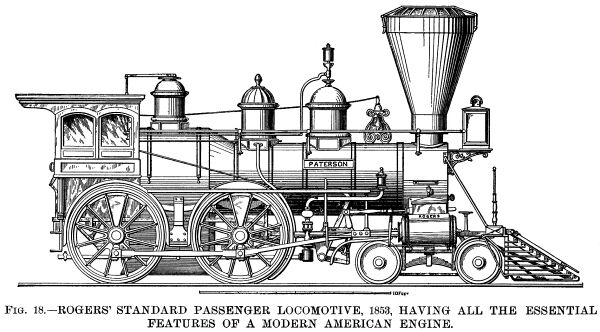
and so we have in the year 1853 an engine possessing all the essential
features of a modern American locomotive, which is shown in Fig.
18. It had the Stephenson firebox, with the peculiar inclined
or tapered joint between it and the barrel of the boiler, making
what is known as the wagon top boiler. The latter was an American
invention. A large number of these engines were built by Mr. Rogers
for various railroads. They had the link motion. The cylinders
were 16 in. diameter by 22 in. stroke, and the driving wheels
were 5 ft. in diameter, although the size of the latter was varied
in different engines. Referring back
to Fig. 12, it will be seen that Campbell’s engine,
although it has the Stephenson firebox, four coupled driving wheels,
with cylinders connected to the forward pair, and a leading truck,
does not possess all the essential features of the modern locomotive,
because the frames are outside and of plate iron and wood. The
cylinders are inside connected, and it has no equalizers. Fig.
13 has outside cylinders, leading truck, inside frames and
equalizers, but the frames are of plate iron and wood, the cylinders
are connected to the rear driving wheels, and the firebox is of
the Bury pattern Fig. 15 has the bar frame, and begins
to look more like an American engine, having the equalizers and
the cylinders connected to the, forward driving wheels; but the
cylinders are inclined, and the outside frame for the running
board and objectionable Bury firebox are still retained, and the
reversing gear is the hook motion. Engineers up to that time were
afraid of spreading the truck wheels too far apart; hence the
necessity of inclined cylinders but in 1850 Mr. Rogers designed
a spread truck, which permitted the cylinders to be dropped down
to a horizontal line, and in the same year the wagon top boiler
was introduced in the practice of the Rogers Locomotive Works;
and so we have in the year 1853 an engine possessing all the essential
features of a modern American locomotive, which is shown in Fig.
18. It had the Stephenson firebox, with the peculiar inclined
or tapered joint between it and the barrel of the boiler, making
what is known as the wagon top boiler. The latter was an American
invention. A large number of these engines were built by Mr. Rogers
for various railroads. They had the link motion. The cylinders
were 16 in. diameter by 22 in. stroke, and the driving wheels
were 5 ft. in diameter, although the size of the latter was varied
in different engines.
In 1857 Mr. Bissell patented a four wheeled truck, having its
frame extended rearwardly and pivoted to the engine frame. The
truck, therefore, swung from this pivot instead of on a central
pin, and the engine rested on a pair of V shaped inclined
planes 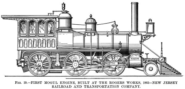 midway between
the two axles. The inventor claimed that a truck on his plan adjusted
itself to the curvature of the track better than one of the ordinary
plan. Mr. Hudson, of the Rogers Locomotive Works, was one of the
first to recognize the value of Bissell’s invention, and
applied it to a locomotive in 1858. In the same year Bissell patented
the single axle or pony truck, as it is often called. This was
constructed on substantially the same principle as his four wheeled
truck and is now in common use. midway between
the two axles. The inventor claimed that a truck on his plan adjusted
itself to the curvature of the track better than one of the ordinary
plan. Mr. Hudson, of the Rogers Locomotive Works, was one of the
first to recognize the value of Bissell’s invention, and
applied it to a locomotive in 1858. In the same year Bissell patented
the single axle or pony truck, as it is often called. This was
constructed on substantially the same principle as his four wheeled
truck and is now in common use.
On the death of Mr. Rogers, which occurred in 1856, the business
of Rogers, Ketchum & Grosvenor was reorganized under the title
of the Rogers Locomotive and Machine Works, and Mr. William S.
Hudson was appointed superintendent. Mr. Hudson was a pupil of
George Stephenson’s, and was one of the foremost locomotive
engineers of his day. Under his supervision, the first Mogul engine,
Fig. 19, built at the Rogers works, was completed in 1863
for the New Jersey Railroad and Transportation Company, now the
New Jersey part of the Pennsylvania Railroad. This engine had
six coupled wheels and the Bissell pony truck previously described,
with swing links patented by Mr. Alba F. Smith, and also an equalizing
lever from the truck to the springs of the forward driving wheels.
This equalizing arrangement was invented and patented by Mr. Hudson.
The cylinders were 17 in. diameter by 22 in. stroke. Driving wheels
4 ft. 6 in. in diameter. Weight about 35 tons. A very large proportion
of the weight of a Mogul engine rests on the driving wheels, which
makes it the most useful and popular freight engine of to-day.
The rapid increase of traffic during the period under notice
demanded a still more powerful freight engine, and in order to
secure the necessary amount of adhesion, Mr. Alexander Mitchell,
master mechanic of the Lehigh and Mahoning Railroad, designed
in the year 1866 an eight coupled engine, and it was named Consolidation.
This name was suggested by the consolidation of the Lehigh and
Mahoning with the Lehigh Valley Railroad, which had just then
been consummated.
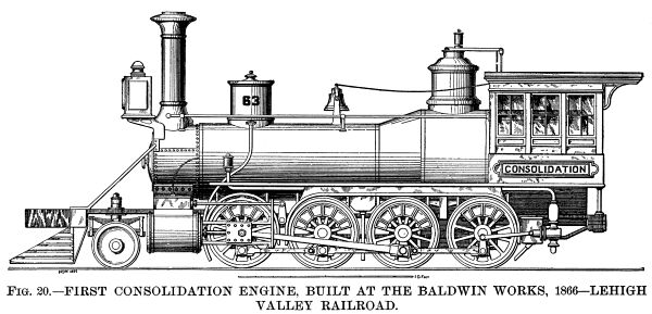 This historical
locomotive is shown in Fig. 20, and it is interesting to
note that both the Mogul and Consolidation engines of the present
day have not been altered in any essential particular except in
dimensions, which reflects great credit on their designers. The
Consolidation was built at the Baldwin Locomotive Works, and its
principal dimensions were: Cylinders, 20 in. diameter by 24 in.
stroke; driving wheels, 48½ in. in diameter. The pony truck
was equalized with the front driving wheels. Weight about 45 tons.
The boiler was fed by one injector and two feed pumps; the latter
were worked by return cranks on the rear driving wheels, as shown.
Pumps have now practically become obsolete. They gave much trouble
by freezing in cold weather, and many vexatious delays were caused
by "failure of the pumps." This historical
locomotive is shown in Fig. 20, and it is interesting to
note that both the Mogul and Consolidation engines of the present
day have not been altered in any essential particular except in
dimensions, which reflects great credit on their designers. The
Consolidation was built at the Baldwin Locomotive Works, and its
principal dimensions were: Cylinders, 20 in. diameter by 24 in.
stroke; driving wheels, 48½ in. in diameter. The pony truck
was equalized with the front driving wheels. Weight about 45 tons.
The boiler was fed by one injector and two feed pumps; the latter
were worked by return cranks on the rear driving wheels, as shown.
Pumps have now practically become obsolete. They gave much trouble
by freezing in cold weather, and many vexatious delays were caused
by "failure of the pumps."
Mr. H. J. Giffard, a French engineer, discovered that the motion
imparted by a jet of steam to a surrounding column of water was
sufficient to force it into the boiler from which the steam was
taken. In July, 1858, he patented his invention of the injector,
and the various inspirators now in general use for supplying steam
boilers with water are all constructed on the model of the Giffard
injector.
In these days of "continuous brakes," it seems remarkable
that the early locomotives were absolutely without any retarding
mechanism; and even down to the medieval period of railway history,
the fastest English trains were run with only a hand brake on
the tender, and a similar brake, worked by the guard, in the brake
van. When the tender weighed only 10 or 15 tons and the brake
van less, this system was woefully inadequate, and many frightful
accidents resulted. American trains were far better equipped in
this respect, and at a very early period all our cars, both freight
and passenger, were provided with hand brakes. In the year 1833,
Robert Stephenson patented a steam brake for locomotive engines,
and in the following year the device was applied to an engine
on the Liverpool and Manchester Railway. It was successful, but,
like the link motion, never came into general use until years
afterward, when the so-called "steam driver brake" was
introduced, being substantially the same as Stephenson’s
design of 1833.
As we have not space to examine the numerous forms of power
brakes that have come and gone during the last fifty years, it
will suffice to say that the invention of continuous brakes, which
act on all the wheels of the train simultaneously, is the most
important one of modern times, inasmuch as their adoption has
not only rendered possible the present high speeds, but has done
more in the way of saving life and property than any other invention
connected with railways.
Various systems of steam, hydraulic and vacuum brakes have
been tried, and also brakes applied by the inertia of the moving
train with more or less success, but it appears that brakes worked
by air pressure are the most efficient and reliable.
George Westinghouse, Jr., introduced his continuous air brake
in 1869 upon a train on the Pittsburgh, Cincinnati, Chicago and
St. Louis Railway running out of Pittsburgh. The brake was non-automatic,
but in 1873 he made a very important improvement by placing his
automatic brake on the Reading Railway. In this arrangement all
the brakes are automatically applied if the train parts or any
of the cars run off the rails. The original automatic system has,
however, been supplanted by the quick action automatic brake,
introduced by Mr. Westinghouse in 1886, which makes the use of
air brakes possible on long freight trains, so that a train of
50 standard freight cars, having a total weight of nearly 2,000,000
pounds, measuring over 1,900 feet in length and traveling at the
rate of 37 miles an hour on a level, can be stopped in the remarkably
short time of 15 seconds without skidding the wheels. In a separate
test to show the rapidity of application, it was found that the
brakes went fully on within two seconds from the tune the engine
driver opened his brake valve. This system is undoubtedly the
best in the world, and does great credit to Mr. Westinghouse.
It now only remains to glance at a few locomotives of modern
construction, as there is practically no difference between the
engines of to-day and those already described, except in dimensions
and weight.
As in 1836 it was found necessary to build four coupled engines
for heavy freight service, so, about fifteen years ago, six coupled
engines for heavy passenger service came into the field, and it
is a noteworthy fact that the fastest speed ever recorded was
attained by a six coupled passenger engine, No. 564, on the Lake
Shore and Michigan Southern Railway, October 24, 1895, when a
special train, weighing 304,500 lb., was conveyed from Erie to
Buffalo Creek (86 miles) in 1 hour 10 minutes 46 seconds = 72.92
miles an hour. During this trip 33 consecutive miles were made
at the rate of 80.6 miles an hour, 8 miles at 85.44 miles an hour,
and 1 mile was covered at the rate of 92.3 miles an hour. This
engine weighs 56½, tons, it has a leading four wheeled
truck, the cylinders are 17 in. in diameter by 24 in. stroke,
and six driving wheels, 5 ft. 6 in. in diameter, which, at 92.3
miles an hour, would make 469 revolutions per minute. The engine
was built by the Brooks Locomotive Works, Dunkirk, N. Y.
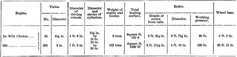
The left hand portion of Fig. 5 shows the celebrated
"999," on the New York Central and Hudson River Railroad.
It is the latest development of the American eight wheeled locomotive,
and the picture gives a good idea of the grandeur and beauty of
its proportions, when compared with the De Witt Clinton. It was
designed by Mr. William Buchanan, chief of motive power of the
above named railroad. The center line of the boiler is no less
than 8 ft. 11½ in. from the rails, and it is remarkably
steady at the highest speeds.
The Empire State Express covers 440 miles in 8¼ hours
= 53.33 miles per hour, including four stops, and this engine
hauls the train over a portion of the route. It was exhibited
with the De Witt Clinton at the Columbian Exposition, and a comparative
table of the dimensions of the first and latest New York Central
engines will be of interest.
This article would be incomplete without touching on "compound"
locomotives. To those who are not familiar with the subject, it
will be well to explain that in ordinary or "simple"
engines, the steam, after having done its work in the cylinders,
is released through the exhaust pipe into the chimney; but in
a compound engine, the steam from the boiler is admitted to one
cylinder only, called the "high pressure" cylinder,
and at the end of the stroke is exhausted to the next cylinder,
called the "low pressure" cylinder, and from thence
through the exhaust pipe to the chimney in the usual way. The
steam is thus made to do its work twice over by virtue of its
expansive force. Broadly speaking, compound locomotives may be
divided into three classes, viz., those having two, three and
four cylinders. Some very good two cylinder compounds have been
built by the Richmond Locomotive Works, which show an economy
of fuel consumption of about 25 per cent. A fine two cylinder
compound engine, No. 1 may be seen every day working in the Grand
Central Station yards in this city. It was designed by Mr. William
Buchanan, and is doing good service. A large number of tree cylinder
compounds are running on the London and Northwestern Railway,
of England, designed by the locomotive superintendent of that
line, Mr. F. W. Webb. These engines show a saving of fuel of about
25 per cent.
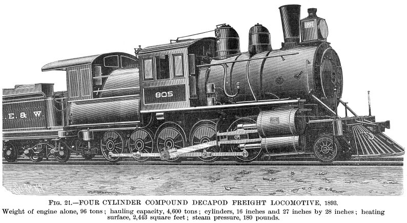
Fig. 21 illustrates one of the best examples of a four
cylinder compound locomotive. It is of the Vauclain type, and
was built by the Baldwin Locomotive Works for the New York, Lake
Erie and Western Railroad for heavy freight service.
The cylinders are arranged in pairs, the piston rods engaging
a common crosshead. The cylinders are 16 in. and 27 in. in diameter
by 28 in. stroke. The engine alone weighs 96 tons and has a hauling
capacity of 4,600 tons on a level. It is worth while to compare
this with the load drawn by the first Baldwin engine, Fig.
10.
It may be remarked that engineers are much at variance on the
question of compound locomotives; many men of the highest standing,
while admitting that a certain success has been attained by compound
engines, maintain that the economy in fuel is counterbalanced
by the disadvantages inherent to the greater complication of machinery
and by the extra cost for repairs. Notwithstanding this, it seems
probable that the compound engine is the locomotive of the future,
and that of the two cylinder type, as being the least complicated
and costly.
The writer takes pleasure in thanking Mr. J. Elfreth Watkins,
curator of the National Museum, Washington; Mr. Theo. N. Ely,
chief of motive power of the Pennsylvania Railroad; Mr. R. S.
Hughes, president of the Rogers Locomotive Company; Mr. William
Buchanan, chief of motive power of the New York Central and Hudson
River Railroad; the Baldwin Locomotive Works; the Westinghouse
Air Brake Company; Mr. M. N. Forney, M.E.; and Mr. Clement E.
Stretton, C.E., of Leicester, England, for the valuable data and
drawings they have kindly placed at his disposal.
Antebellum RR
| Contents Page
|


