|
THE NEW BROOKLYN TERMINAL STATION OF
THE BROOKLYN BRIDGE.
Engineering News—July 4, 1895
(With Inset.)
The new terminal arrangements and stations of the cable railway
over the Brooklyn Bridge, which have been the subject of much
discussion, and work upon which was delayed for so long that it
began to seem doubtful whether the plans would ever be carried-out,
are now well advanced, and it appears probable that the new system
will be ready to be put in operation during the present year,
when it will soon be apparent whether the expected increase in
traffic facilities will be attained. As to the terminal arrangements,
it may be well to explain that as now constructed there are two
side platforms separated by two tracks. Each incoming train discharges
its passengers at one platform and is then hauled by a locomotive
out beyond the station and pushed back on the other track to receive
passengers at the other platform. With the new arrangement there
will be two island platforms, and four tracks. Incoming trains
will run on either side of the arrival platform alternately, and
will then be hauled out and pushed back on one or other side of
the departure platform. This new arrangement is but an elaboration
of the present tail-switching system, but it is claimed that trains
can be run more frequently, and thus avoid the present crowding
during the busy hours of the morning and evening. To avoid
the use of facing switches, the rails of the two incoming and
two outgoing tracks will be laid continuously across the bridge,
being laid close together to form a double gantleted track along
each present single track. This will necessitate the use of a
duplicate cable and cable driving plant.
The New York terminal was described and illustrated in detail
in our issue of Nov. 8, 1894, and we give herewith similar particulars
of the Brooklyn terminal, general descriptions of which were given
in our issues of Feb. 9 and April 20, 1993. Work is progressing
steadily on both terminals, and the Brooklyn station is now approaching
completion. The reconstruction of the New York terminal is complicated
by the fact that it has to be carried out on the site of the present
station, but while the new Brooklyn terminal is beyond the present
terminal, yet the design of the station is more complicated, for
the reason that provision has had to be made in it for platforms
for the elevated railways above the level of the
platforms of the bridge railway. The difficulties of carrying
out these works were described in our issue of April 18, 1895.
The new Brooklyn station is located on the western side of
Washington St., extending over Sands and High Sts. It is intended
chiefly for the use of passengers over the bridge, but provision
is made also for the accommodation or passengers to or from the
Brooklyn Elevated R. R. and the Kings County Elevated R. R. and
the several surface railways reaching this terminal.
In plan the main part of the station is rectangular, 357 ft.
6 ins. long and 90 ft. wide, with two opposite projections or
wings near each end, each 25 ft. long and 56 ft. 8 ins. wide,
while extending from the northern end is an approach viaduct connecting
the station with the bridge. The station has three floors: On
the first or ground floor are retiring rooms and two ticket booths;
on the second floor, placed longitudinally, are two passenger
platforms and four tracks for the bridge railway, and on the third
floor, placed transversely in each opposite pair of wings, are
three passenger platforms and two tracks for the Brooklyn Elevated
R. R., and also an intermediate longitudinal gallery connecting
these wings. Between the first and second floors are two stairways,
and between the second and third floors are nine stairways. At
each end of the intermediate, longitudinal gallery, and connecting
it with the three platforms of the elevated railway at that end
by a stairway to each platform, is a stairway and gallery which
spans the two tracks of the elevated railway. At each end of the
bridge station are stairways leading directly from the elevated
railway platforms to the bridge footway or to the street. There
are ticket-sellers' boxes on the second and third floors, near
the entrances to the stairways connecting the passenger platforms
on either of these floors with those above or below.
The general system of construction is similar to that of the
New York station, already described, and the general exterior
appearance is also similar. The framework of the station building
is of vertical columns for the outer walls and intermediate supports,
horizontal girders and beams for the second and third floors,
and trusses for the roofs. The outer walls are of paneled and
shaped cast or wrought metal, with ample window area, and the
interior walls and partitions are of brick or wood and glass.
The floors are of brick arches between the girders and beams surfaced
with concrete, and the roofs are of wood on steel purlins, covered
with sheet metal, slate and glass. Ornamental work of neat architectural
design in the form of cast iron moldings, cornices, paneling,
etc., is attached to the sides and gable ends of the structure,
but no attempt has been made at an elaborate architectural design.
The finished color of the ironwork is a light yellow. The approach
viaduct is of wrought iron or steel vertical columns and horizontal
girders and beams connected together; between the girders and
beams are brick or terra cotta arches, surfaced with concrete.
The contract for the station building, not including foundations,
tracks or machinery, was let to the Phoenix Bridge Co., of Phoenixville,
Pa.
The greater part of the station has been erected without trouble,
as it is south of the present station, and only interferes with
the south end of the latter. The present station will be removed
and a viaduct approach built on its site, being a continuation
of the present approaches, the grade of the tracks being unchanged
through the station. The new station will have straight tracks,
thus avoiding the inconvenience and danger incident to the curved
track., and platforms in the present station The roadways have
been widened by moving the stone parapets about 17 ft. further
out, thus giving a more convenient connection with Sands St. The
sidewalks on the Plaza and Washington St. sides of the station
are to be covered by roofs carried by brackets riveted to the
columns, as shown on the cross-section in our issue of April 20,
1893. The trainshed of the station has at each end a trainshed
at right angles for the Brooklyn Elevated Railway, the latter
crossing above the bridge railway tracks. The total length, including
the transepts, is 355 ft. 10 ins. c. to c. of end posts, and the
distance c. to c. of elevated railway stations is 261 ft. 4 ins.
The width of bridge trainshed is 88 ft. 10 ins. c. to c. of columns.
At the level of the platforms of the elevated railway is a
gallery 16 ft. wide, suspended from the roof trusses and running
the whole length of the station between the elevated railway trainsheds
and stairways 6 ft. wide lead from this and connect the side and
island platforms of the elevated railway with the two island platforms
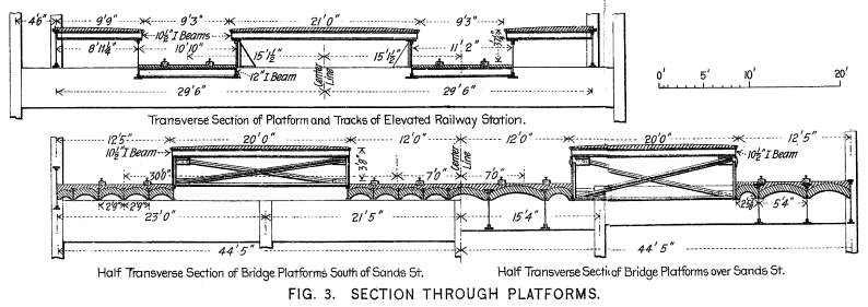
of the bridge railway below. The elevated railway has two tracks
in each station, separated by a platform 21 ft. wide, and having
side platforms 9 ft. 9 ins. wide. The clear height of edge of
platform above rail base is 3 ft. 7¼ ins., and the clear
width between platform edges is 9 ft. 3 ins. The bridge station
has four tracks; one at each side and two in the middle of the
station, separated by two island platforms 270 ft. long and 20
ft. wide. The height of edge of platform above rail base is 3
ft. 8 ins., and the clear width between platform is 24 ft. and
between platform and side of building 12 ft. The middle tracks
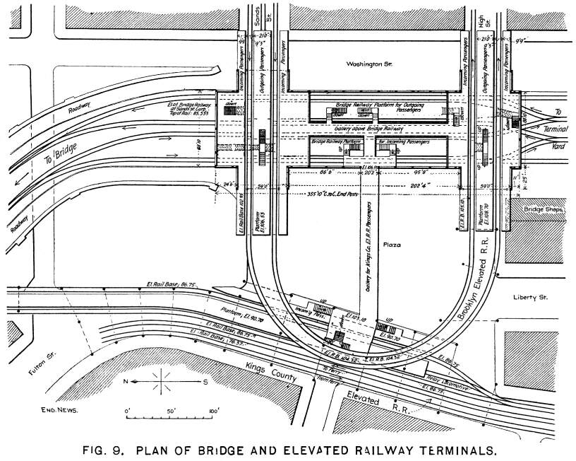
are 14 ft. c. to c. The two elevated railway stations will be
connected by a loop over the Plaza and Fulton St., as shown on
the plan, Fig. 9. The elevated station at the north end of the
bridge station is already in operation. This loop is a plate girder
structure with solid floor, and crosses above the Kings County
Elevated R. R. structure.
The bridge trainshed is spanned by roof trusses 20 ft. 6 ins.
apart, of the type shown in Fig. 4, which represents one of the
main trusses, as indicated in the plan, Fig. 3. The span of truss
is 88 ft. 10 ins. c. to c. of columns, or 87 ft. 4 ins. back to
back of chord cover plates. The depth of truss is 13 ft. at the
back and 10 ft. 4 5-16ins. at the center. The angle of rise of
roof or upper chord is 26 deg. 33' 53". The lower chord has
a radius of 82 ft. 21/8 ins. in the central
part, decreased to 12 ft. 6 13-16 ins. radius at the ends. The
top chord is horizontal for a width of 22 ft. 3 ins. at the middle
of the truss, and above this portion is a monitor or ventilator
roof. The diagonal trusses, or valley trusses, B, Fig. 5, used
at the intersection of the roofs of the bridge and elevated railway
stations are 110 ft. 03/8 in. long, 13
ft. 7 ins. at the back and 10 ft. 4 15-16 ins. deep at the middle.
The top chord has an angle of 21 deg. 41' 17" at each side,
and is horizontal at the middle of the truss for a width of 28
ft. 0½ in. At the center of the span the chord angles are
made continuous in one truss of each pair, while in the other
trusses the chord angles and cover plates are cut. Generally the
rivets are ¾ in. diameter. Rivet holes in steel, if punched,
are afterward reamed to size, and not less than 1-16 in. of metal
removed. In case of slight misfit the holes are reamed, no drifting
being allowed. The ventilator roof trusses are 22 ft. 9¼
ins. span, spaced 20 ft. 6 ins., 25 ft. 4 ins. and up to 35 ft.
10 ins. apart. They are connected by riveted trusses with parallel
chords, the depth of truss being 2 ft. 4 ins. The brace rods of
the wind bracing pass through filler plates just below the top
chord, and through the end posts. The general arrangement of wind
bracing and connections is similar to that of the New York station,
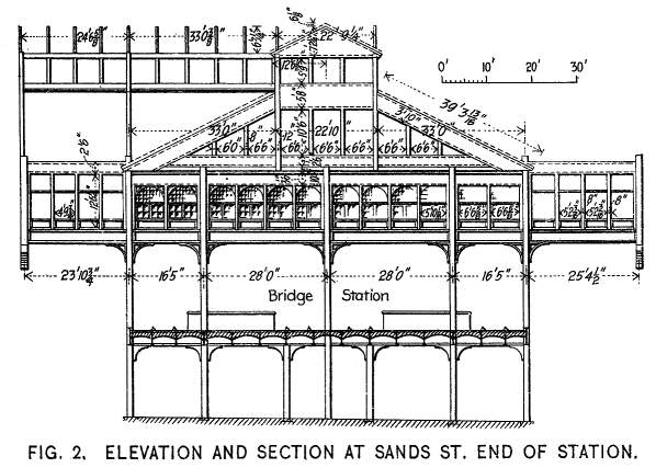
which we have already illustrated. The height from the street
level at Sands St. is 26 ft. to the platforms of the bridge railway,
and 44 ft. to those of the elevated railway.
The main roofs are covered with heavy slates of even tint and
uniform size, 8 ins. wide and 16 ins. long, with the lower corners
chipped off so as to form a hexagonal outline, they are laid over
waterproof tarred roofing felt, the lap not less than 2½
ins., and completely bonded in the heading courses, at the eaves
and elsewhere, and each is secured in place by two copper nails.
Horizontal slats of sheet metal, hung centrally on pivots, will
be inserted in openings in the sides which support the ventilator
roofs. The flashings, counter flashings, ridge rolls, gutters
and leaders will be of sheet copper, weighing not less than 20
ounces per sq. ft. The roof coverings of sheet metal are of bright
charcoal IX. tin in sheets 20 x 10 ins. The ventilator slats and
the panels, moldings and other par's for architectural finish
of sheet metal are of galvanized iron no less than 1-30 in. thick.
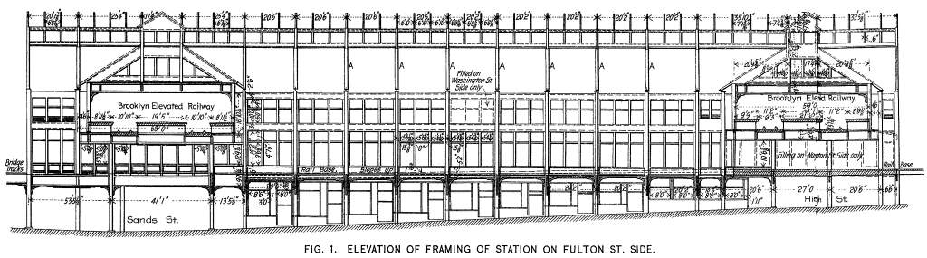
All the end or gable trusses have solid web plates of ¼-in.
metal, as shown by Fig. 1, which are relieved by ornamental work
in cornices, moldings and panels, as already mentioned.
In open spaces in the main roofs and ventilator roofs are inserted
roof lights, each consisting of plates of rolled or hammered glass
¼-in. thick, laid without lap or putty in a metal sash,
which is part of the roof frame itself. Efficient means are provided,
by the use of gutters on the under side and a part of the metal
sash or otherwise, to collect and conduct away without dripping
any moisture which may condense on the glass; also to prevent
water which may fall on other parts of the roof from flowing over
the roof lights. The joints between the glass and sash and between
the sash and adjacent parts of the roof are to be made so as to
be and remain thoroughly watertight. The Paradigm system is used,
as shown in Fig. 8.
At the shops where the new metal work is wrought or cast, as
well is at the site where the old metal is changed, all metal
surfaces brought into contact before riveting together are given
a heavy coat of linseed oil made thick with red lead, freshly
and thoroughly mixed and so put on that the spaces enclosed are
completely filled. Before leaving the shops, all the new work
is given a thick coat of this paint, suitably shaded with lampblack,
and well brushed on, and allowed to dry hard before the parts
are shipped. The tin roofing sheets, before laying, are given
a coat of the same paint oil each side. After erection all of
the exposed woodwork will have a thick coat of linseed oil; then
the joints and joint holes of the metal work will be filled flush
and even with a suitable cement, and those of the woodwork well
puttied, and the surfaces smoothly sand-papered. The lower parts
of the columns and the exterior surfaces of the cast iron leaders
and drain pipes, which will be below the first floor level, have
a thick coating of hot bitumen, tempered so as to be tough and
hard when cold, and finally two more coats of linseed oil, or
of paint, for ornamentation of different colors for the several
parts, will be applied to all the exposed wood and metal work.
The roofing slates, after they are laid, and, if so required,
certain parts of the brick work, will have one coat of linseed
oil. All rust, cinder and sand scales must be removed from, metallic
surfacer, and wire brushes or otherwise, and all surfaces made
clean and free from moisture when a coat of oil or paint is applied,
and this coat must be dry and hard before another one is put on.
The oil used is to be the best light-colored boiled linseed. The
pigments will be chiefly red or white lead, mixed with other pigments
to secure the desired colors, the paint being thoroughly intermixed,
with a due proportion of oil and pigment. The entire space between
the Plaza and the Washington St. sidewalks and the sidewalks on
Sands and High Sts. will be enclosed, forming a large main hall,
with toilet rooms adjoining and having several ticket offices.
In each side panel will be a door and window, as shown, by the
elevation, but, of course, in cold weather a number of these entrances
will be closed. Provision will be made for warming this hall.
On the upper floor will be ticket offices for passengers from
the elevated railways. Kosmocrete paving is laid around the building,
and the main floor is paved with asphalt.
The general arrangement of tracks is shown in the sketch plan,
Fig. 9, being similar to that at the New York station, except
that at the north end the tracks lead out on a curve of 260 ft.
radius, while at the south end there are connections to the storage
tracks on the elevated yards, which yards are carried by a structure
of steel columns and girders with brick arches. This structure
is 100 to 140 ft. wide, and extends 870 ft. from the station back
to Tillary St., where it is 25 ft. above the ground. The tracks
in the present station are level, but there is a grade of 1% up
from Sands St. and through the new station. There are eight storage
tracks on this structure, accommodating 100 cars, and there are
also tracks for repairs, etc. Underneath is a space for storing
supplies, etc., and at one side are the shops. The course of the
switching movements can be followed out by the arrows marked on
the tracks.
The arrangement of the bridge station and the elevated railway
stations appears somewhat complicated from this plan, but will
be more readily understood by a comparison of the differences
in levels, as shown by the figures marked on the plan. Fulton
St. is here on a steep slope rising from the river, and the two
main tracks of the Kings County Elevated R. R. ascend this grade
from the terminal station at the ferry by a grade of about 4%,
a dead-end spur track being carried out on the level to a platform
for the use of passengers to and from the bridge. Sands St. and
High St. slope up from Fulton St. to the bridge station, and the
grade of the bridge tracks is slightly lower than that of the
spur track above noted. Above the bridge tracks is the grade of
the Brooklyn Elevated R. R. tracks, which cross above the bridge
railway tracks, and will also cross over the tracks of the Kings
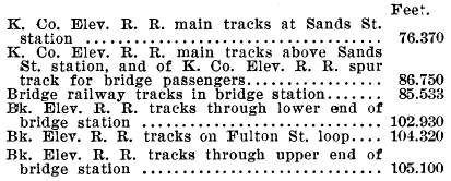
County Elevated R. R. when the loop track is completed. The principal
elevations of the parts of the different tracks in the station
above water level in the East River, adopted as a datum plane,
are as follows:
The traveler used in erection, Fig. 10, is about 80 ft. wide
over the side towers, and has a clear span part, the elevation
above the traveler rails being 22 ft., 46 ft. and 74 ft., respectively,
while the total height to the top of the upper derrick mast is
92 ft. The high part of the structure is 34 ft. long, but the
lower panel is carried out to a length of 59 ft., as shown in
the cross-section, so that the first deck is of extra length,
and forms a working platform to carry the hoisting engines and
boilers, etc. The derrick booms are 18, 26, 30 and 40 ft. long.
Each side of the traveler is carried by eight 21-in. wheels on
a track of standard gage. This traveler was erected on tracks
in the elevated terminal yard above mentioned, and commenced work
at the south end of the new station, proceeding northward until
it encountered the south end of the old station.
Brooklyn Bridge | Bridge Page
| Contents Page
|


