|
THE BALDWIN LOCOMOTIVE WORKS — 1912
Mallet Articulated Locomotives
THE maximum tractive force which can be developed by a locomotive
depends primarily upon the weight carried on the driving wheels.
With given track conditions, there is a maximum load per wheel
which cannot be safely exceeded; hence the number of driving wheels
used must be such that the weight necessary for adhesion can be
carried without overloading the rails. Because of wheelbase limitations
it is not practicable to couple more than five pairs of driving
wheels in one group; and on some roads even this would require
a rigid wheelbase of prohibitive length. If, therefore, additional
wheels must be used to carry the required weight, it is necessary
to divide them into two groups and to arrange at least one group
in the form of a truck in order to keep the rigid wheelbase within
reasonable limits. With such a plan a locomotive of high tractive
force can be designed with a long total wheelbase and moderate
wheel loads, and can at the same time traverse curves without
difficulty.
The most successful type of articulated locomotive at present
in use on American railways is the Mallet. These locomotives were
first introduced on European railways, in 1889, by M. Anatole
Mallet, a noted French engineer. They were first built by The
Baldwin Locomotive Works in 1904, for the American Railroad of
Porto Rico, a metre gauge line; but it was two years later before
they were employed to any extent on railways in the United States.
The use of Mallet locomotives in this country was at first
restricted to pushing service on mountain grades. For this they
are admirably adapted, as because of their great tractive force
the number of helper engines required to perform a given service
is reduced to a minimum, as is also the amount of tonnage reduction
necessary when transferring a train from a level to a mountain
division.
With a given allowable weight per axle, a Mallet locomotive
can be built to develop twice as much tractive force as an engine
of the ordinary type, because twice as many pairs of driving wheels
can be placed under it. The weight necessary for adhesion can
thus be safely carried, and a proportionate increase in the tractive
force developed. by building the locomotive of suitable dimensions.
This high tractive force, however, can be utilized only at moderate
speeds, such as are maintained in heavy freight and mountain service.
As in other types of locomotives, the tractive force of a Mallet
falls off with an increase in speed; and hence a point is soon
reached where the large adhesion weight cannot be utilized. It
is important that Mallet locomotives be specially designed for
the required service, and used in that service to obtain the most
satisfactory results.
In certain cases, Mallet locomotives are used to advantage
in road service; as, for example, where heavy tonnage trains are
hauled over long grades at moderate speeds. Such work requires
locomotives capable of exerting a high tractive force for sustained
periods of time. The locomotives for the Clinchfield road are
operating under these conditions. Several other locomotives used
in road service, are described. In each case the engines were
specially designed for the particular service required.
The general features of the Mallet type of locomotive are well
known, and only brief reference need be made to them in this connection.
The cylinders are four in number, and they are arranged on the
compound system; the high-pressure cylinders driving the rear
group of wheels, and the low-pressure the forward group. The front
frames are hinged to the rear frames in such a way that when the
engine enters a curve, the front group of wheels swings about
a hinge pin located on the center line of the engine between the
high-pressure cylinders. The boiler is held in rigid alignment
with the rear frames, and is supported on the front frames by
sliding bearings. Flexible pipes convey the steam from the high
to the low-pressure cylinders and from the latter to the smoke-box.
Large locomotives of this type can be designed to traverse the
sharpest curves usually encountered in trunk line operation.
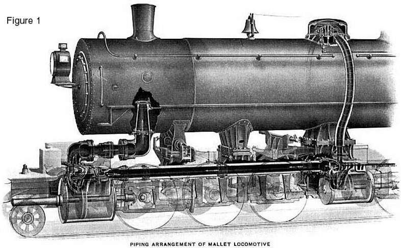
The first standard gauge Mallet locomotives built by The Baldwin
Locomotive Works were completed in 1906, for the Great Northern
Railway. These locomotives are of the 2-6-6-2 type and the general
arrangement of the steam piping is like that shown in Figure 1.
The steam dome is placed immediately above the high-pressure cylinders
and the live steam is conveyed from the throttle to the steam
chests through external, rigid pipes. The receiver pipe connecting
the high and low-pressure cylinders, is placed on the center line
of the locomotive between the frames, and is fitted with a ball
joint at the back end. The center line of the ball joint coincides
with the center of the articulated frame connection, so that the
length of the receiver pipe is constant regardless of the relative
positions of the front and back frames. A slip joint is
placed near the front end of the pipe, to compensate for expansion
and contraction. The exhaust pipe is fitted with a ball joint
at each end and a slip joint in the middle.
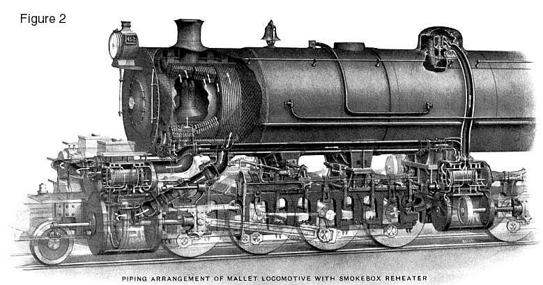
The illustration in Figure 2, shows the arrangement of piping
used when a Baldwin reheater is installed in the smoke-box. The
high-pressure exhaust is carried forward through external pipes,
which discharge the steam into the lower reheater drums. The reheater
is arranged like a Baldwin superheater. The steam passes from
both sections of the reheater into the flexible receiver pipe,
which is placed on an angle under the smoke-box. This pipe is
necessarily fitted with a ball-joint at each end and an intermediate
slip joint.
On many of the larger Mallet locomotives built by The Baldwin
Locomotive Works, the boiler is constructed in two sections, which
are united by a separable joint. The front boiler section contains
a feed-water heater. An open chamber is placed between the feed-water
heater and the boiler proper, and the separable joint surrounds
this chamber. The joint is formed by two external rings, which
are riveted to the front and rear boiler sections respectively.
These rings are butted, with a V-shaped fit, and are held together
by horizontal bolts which are placed at close intervals around
the entire circumference.
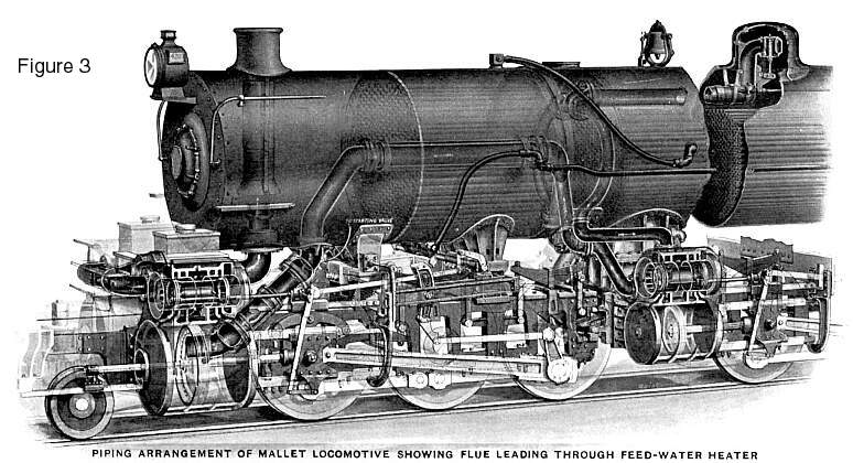
The above illustration shows the forward section of a boiler
of this type. The arrangement is that applied to the passenger
locomotives for the Southern Pacific Company. In this case the
high-pressure exhaust enters a horizontal pipe, which traverses
the feed-water heater through a large flue. This pipe communicates
with the flexible receiver pipe, by means of a cast iron elbow
located in the smoke-box. In this way, although the reheating
surface is small, the piping is exposed as little as possible
to the cooling effects of the atmosphere.
The illustration further shows the construction of the feed-water
heater, which is traversed by horizontal fire-tubes and is kept
constantly filled with water. The injectors, when in operation,
force water into the bottom of the heater, and the water is discharged
through an outlet at the top, and is then forced into the evaporating
section of the boiler. By this means the feed is heated to a temperature
of about 250 degrees. This arrangement of water-heater has been
applied, with marked success, to a large number of locomotives.
In the case of the locomotives for the Virginian Railway and
the Duluth, Missabe and Northern Railway, the single pipe in the
water heater is replaced by a nest of small tubes, which provide
considerable reheating surface.
The boilers of two of the locomotives for the Atchison, Topeka
and Santa Fe Railway, embody several special features of construction.
The first locomotive has a rigid boiler of the separable type.
The front boiler section contains, in the following sequence,
a smokebox, feed-water heater, intermediate chamber, reheater
and superheater. The reheater and superheater are of the Buck-Jacobs
type. They are built into the boiler shell, and are separated
by a tube sheet; while one set of tubes traverses bofh heaters.
The steam, guided by internal baffle plates; circulates through
the heaters and absorbs heat from the furnace gases which are
flowing through the tubes. The steam pipes used on this locomotive
are all placed outside the boiler shell, so that the pipe joints
are easily accessible. Another special feature is the firebox,
which is of the Jacobs-Shupert sectional type as developed by
the mechanical officers of the Santa Fe System. The inside and
outside shells of this firebox are each composed of a series of
channel sections, which are bent to a horseshoe form. The usual
stay-bolts are replaced by plates, which have openings cut in
them to permit the free circulation of steam and water, and are
riveted between the adjacent channels. The construction of this
firebox has been fully explained in the technical press.
 The second
locomotive has an articulated boiler, with each section rigidly
mounted on its respective frames: The flexible joint consists
of fifty rings of high carbon steel, which are ten inches wide
and formed with a slight set, so that when placed adjacent to
one another they form a series of V-shaped joints. The rings have
an outside diameter of seventy-five and one-half inches. They
are riveted together at their inner and outer edges, and form
a bellow’s-shaped structure which is forty-four and three-quarters
inches in length. This is bolted into place between the front
and rear boiler sections. An internal flue, forty-four inches
in diameter, traverses the flexible connection, and is flared
out at the back to fit into the rear boiler section. This flue
prevents ashes and cinders from lodging in the flexible joints. The second
locomotive has an articulated boiler, with each section rigidly
mounted on its respective frames: The flexible joint consists
of fifty rings of high carbon steel, which are ten inches wide
and formed with a slight set, so that when placed adjacent to
one another they form a series of V-shaped joints. The rings have
an outside diameter of seventy-five and one-half inches. They
are riveted together at their inner and outer edges, and form
a bellow’s-shaped structure which is forty-four and three-quarters
inches in length. This is bolted into place between the front
and rear boiler sections. An internal flue, forty-four inches
in diameter, traverses the flexible connection, and is flared
out at the back to fit into the rear boiler section. This flue
prevents ashes and cinders from lodging in the flexible joints.
The superheater, in this boiler, is built into the rear section
while the reheater is built into the front section. Both heaters
are of the Jacob’s type, arranged for outside steam pipe
connections. The superheater is traversed at its center by an
eighteen-inch flue, and the reheater by a six-inch flue; these
flues being provided to facilitate the removal of the boiler tubes.
The tube ends are all accessible by means of chambers in the boiler,
and these chambers can be entered through suitable man-holes.
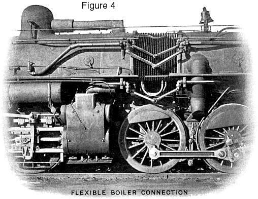
In a locomotive of this type, it is not necessary to have sliding
supports under the forward part of the boiler; and the locomotive
curves with a minimum amount of resistance, and its stability,
when traversing a curve, is not affected. Only one flexible steam
pipe is required, and that connects the high-pressure cylinders
with the reheater. Metallic flexible joints are used in the feed
pipes which pass the boiler articulation.
Figure 5 shows the latest design of articulated frame connection
used on Mallet articulated locomotives built by The Baldwin Locomotive
Works. In this construction the high-pressure cylinder saddle
serves as a support for the cylinders and boiler, and constitutes
part of the main frame of the locomotive. This saddle also carries
the hinge pin, and contains a pocket in which is placed the ball
joint of the receiver pipe. The saddle is of cast steel, made
in two pieces. The upper piece is riveted to the boiler shell,
as a tighter joint can be secured in this way than when the parts
are bolted together. The main frames are bolted to the lower section
of the saddle, and the joint is arranged with a deep slab fit
and is locked by a pair of keys which are driven into a long vertical
key-way with their tapered faces in contact. A similar plan is
used for keying the cylinders to the saddle. The frame connection
is effected by a single radius bar, which also constitutes a strong
transverse brace for the rear end of the front frames. The hinge
pin is inserted from below, and is held in place by a supporting
bolt. The holes for the hinge pin in both the radius bar and saddle
are bushed. As shown in the drawing, the center of the hinge pin
coincides with that of the ball joint in the receiver pipe. The
saddle is cored with a suitable passage, through which steam passes
from the high-pressure exhaust pipes to the receiver pipe.
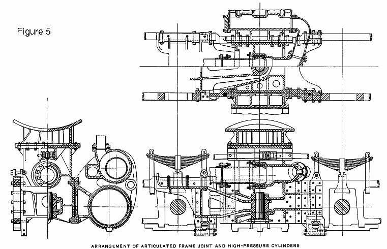
The saddle is made with a forward extension on each side, and
this extension has a slight amount of vertical clearance between
the upper and lower rails of the front frames. Any transference
of weight at this point takes place by actual contact between
the frames. The drawing shows the joint in the reach rod which
connects the reverse shafts of the front and rear engines. This
joint is arranged like a crosshead, and the guides supporting
it are bolted to the inner walls of the saddle. This crosshead,
throughout its entire travel, is so near the center of the hinge
pin, that there is practically no distortion to the movement of
the low-pressure valves when the engine is traversing curves.
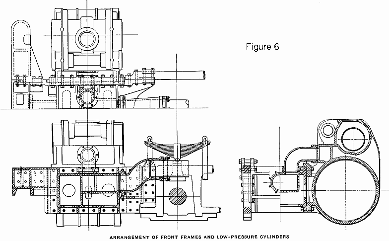
Figure 6 shows the construction at the forward end of the front
frames. The arrangement is in many respects similar to that described
above, except that no support is provided for the boiler. The
casting between the cylinders has cored in it suitable passages
for conveying the steam from the receiver pipe to short elbow
pipes which lead to the low-pressure steam chests.
The arrangements for bolting together the frames, cylinders,
and cylinder saddles, as described above, are exceptionally strong,
and the various parts have such large bearing surfaces that the
chances of their working loose are reduced to a minimum. The cylinders
are so arranged that they can be easily removed without dismantling
the saddles, frames or principal steam pipes. These designs constitute
an interesting illustration of the use of cast steel in heavy
locomotive construction, as they would be impracticable unless
the larger parts (with the exception of the cylinders) were made
of this material.
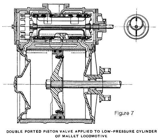 Figure 7 shows
a section through the low-pressure cylinder of a Mallet articulated
locomotive. The steam distribution is controlled by a new design
of double ported piston valve, which in the illustration referred
to, is arranged for outside admission. The valve has the same
effect as an Allen-ported slide valve. This is of special advantage
when the engine is linked up, as the port opening is far greater
than could be obtained in a valve of the ordinary type. The arrows
on the drawing show the course of the steam. This same style of
valve, when used on the high-pressure cylinders, is usually arranged
for inside admission. Figure 7 shows
a section through the low-pressure cylinder of a Mallet articulated
locomotive. The steam distribution is controlled by a new design
of double ported piston valve, which in the illustration referred
to, is arranged for outside admission. The valve has the same
effect as an Allen-ported slide valve. This is of special advantage
when the engine is linked up, as the port opening is far greater
than could be obtained in a valve of the ordinary type. The arrows
on the drawing show the course of the steam. This same style of
valve, when used on the high-pressure cylinders, is usually arranged
for inside admission.
A reliable form of power reverse mechanism is an essential
feature of a Mallet locomotive, in order that the engine may be
handled without undue effort on the part of the enginemen. Figure
8 represents the Ragonnet power gear, a patented device which
is regularly applied to Mallet locomotives built by The Baldwin
Locomotive Works. This device consists of an air cylinder, whose
piston is connected to the reverse shaft of the rear engine by
means of a suitable crosshead and link. Admission of air to the
cylinder is controlled by a 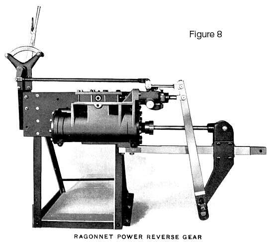 slide valve, and the mechanism is operated by a small
hand lever which is placed in the cab. When the hand lever is
moved to change the cut-off, the valve is displaced from its central
position, air is admitted to one end of the cylinder, and a movement
of the piston follows. The crosshead and valve rod are both connected
to a combining lever, and the arrangement is such that when the
piston moves, the swing of this lever moves the valve back to
its middle position. The mechanism is so adjusted that when the
link blocks have been shifted to give the cut-off desired, the
slide valve closes the admission port and further movement of
the piston ceases. The construction is such that when the gear
is set for any particular point of cut-off, the valve is in its
middle position. Should air leak in at one end sufficiently to
cause a movement of the piston, the valve will at once move, admitting
air to the other end of the cylinder and locking the mechanism.
The inside, or exhaust lap of the valve is considerably greater
than the outside lap, so that air pressure can be held on both
sides of the piston simultaneously. slide valve, and the mechanism is operated by a small
hand lever which is placed in the cab. When the hand lever is
moved to change the cut-off, the valve is displaced from its central
position, air is admitted to one end of the cylinder, and a movement
of the piston follows. The crosshead and valve rod are both connected
to a combining lever, and the arrangement is such that when the
piston moves, the swing of this lever moves the valve back to
its middle position. The mechanism is so adjusted that when the
link blocks have been shifted to give the cut-off desired, the
slide valve closes the admission port and further movement of
the piston ceases. The construction is such that when the gear
is set for any particular point of cut-off, the valve is in its
middle position. Should air leak in at one end sufficiently to
cause a movement of the piston, the valve will at once move, admitting
air to the other end of the cylinder and locking the mechanism.
The inside, or exhaust lap of the valve is considerably greater
than the outside lap, so that air pressure can be held on both
sides of the piston simultaneously.
This gear has proved so reliable in service that ordinarily
no hand reversing mechanism is applied.
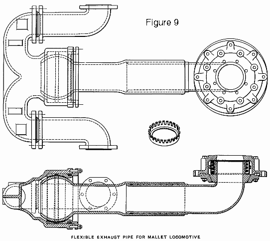 Figure 9 illustrates
the flexible exhaust pipe of a Baldwin Mallet locomotive. Special
attention is called to the construction of the ball joint at the
smoke-box end of this pipe. This joint is placed immediately under
the exhaust nozzle, and is kept tight by a coiled spring. The
spring is always in compression, and is confined within a suitable
casing; so that, when the parts are being dismantled, it cannot
suddenly extend to its free height and thus cause damage. The
construction of the casing is shown in the drawing. The upper
and lower sections are provided with a series of projections,
which interlock and are surrounded by a steel wire ring. Each
projection has a lip extending outwardly, and these lips engage
the ring and hold the sections together. The effectiveness of
the spring in keeping the joint tight is not impaired by reason
of the casing; and the removal and replacement of the spring,
when making repairs, are easily effected. Figure 9 illustrates
the flexible exhaust pipe of a Baldwin Mallet locomotive. Special
attention is called to the construction of the ball joint at the
smoke-box end of this pipe. This joint is placed immediately under
the exhaust nozzle, and is kept tight by a coiled spring. The
spring is always in compression, and is confined within a suitable
casing; so that, when the parts are being dismantled, it cannot
suddenly extend to its free height and thus cause damage. The
construction of the casing is shown in the drawing. The upper
and lower sections are provided with a series of projections,
which interlock and are surrounded by a steel wire ring. Each
projection has a lip extending outwardly, and these lips engage
the ring and hold the sections together. The effectiveness of
the spring in keeping the joint tight is not impaired by reason
of the casing; and the removal and replacement of the spring,
when making repairs, are easily effected.
The drawing also shows the construction of the ball joint at
the front end of the pipe. The ball is seated on two babbitt lined
rings of brass, and these can be adjusted by a packed gland. The
slip joint in the middle of the pipe has a long sliding fit, and
is kept tight by a pair of snap rings and a series of leakage
grooves.
The ball joints in the receiver pipe are similar in construction
to that used at the forward end of the exhaust pipe. The slip
joint in the receiver pipe is fitted with a packed gland, as the
pressure here is sufficiently high to require this form of construction.
The Handling of Mallet Articulated
Locomotives
The handling of a Mallet articulated locomotive presents no
special difficulties. As the high and low-pressure engines each
operate like a single expansion locomotive, it is unnecessary
to introduce complicated features because of the application of
the compound principle. In order to enable the locomotive to develop
full power at starting, it is necessary to provide means for admitting
steam direct from the boiler to the low-pressure cylinders. In
the Baldwin engine, a small pipe is run from a starting valve
in the cab, to the receiver pipe connecting the high and low-pressure
cylinders. By opening the starting valve, steam will pass direct
from the boiler to the receiver pipe and thence to the low-pressure
cylinders, and the locomotive will develop a tractive force up
to the limit of its adhesion. This device is recommended because
of its simplicity and reliability in service.
The flexible pipes which convey the steam from the high to
the low-pressure cylinders, and from the latter to the smoke-box,
should frequently be inspected and tested for leakage; as it is
important that the ball and slip joints be kept tight. The sliding
bearings supporting the boiler on the front frames should be regularly
oiled; also the hinge pin connecting the front and rear frames,
and the joint in the reach rod connecting the front and back reverse
shafts. This joint as usually arranged on Mallet locomotives built
by The Baldwin Locomotive Works, is provided with a crosshead,
which is placed between the inner walls of the high-pressure cylinder
saddle; and is so arranged that the reach rod can accommodate
itself to the swing of the front frames when the engine is traversing
curves.
Reference has been previously made to the separable type of
boiler used on large Mallet locomotives. A boiler of this type
should be fed in the same manner as one of the ordinary design,
as water is simply forced over from the feed-water heater to the
evaporating section when the injectors are in operation. The temperature
of the feed-water is raised to about 250 degrees; hence a certain
amount of scale, depending upon the quality of the water, will
be deposited in the heater, with a corresponding reduction in
the quantity deposited in the boiler. The heater, therefore, should
be cleaned at regular intervals.
In a long boiler of this type the smoke-box gases are comparatively
cool, tests having shown temperatures approximating 450 degrees.
The result is a relatively high boiler efficiency, due to the
large amount of heat absorbed by the water before the gases escape
up the stack.
The high-pressure cylinders of a Mallet articulated locomotive
are lubricated from the cab in the usual manner. The low-pressure
cylinders may be lubricated in the same way, through flexible
pipes. Another method, which has proved convenient and satisfactory,
is to use a pair of force feed oil pumps, which are driven from
the valve motion of the front engine. Flexible piping is thus
dispensed with. In a similar way, the front group of driving wheels
can be supplied with sand from a box placed over the forward deck
plate, and the sand delivered to the rails through rigid pipes.
Pneumatically operated cylinder cocks are frequently used on the
low-pressure cylinders, and the cylinder cock rigging is simplified
by this arrangement.
Before starting a Mallet locomotive on a trip, care should
be taken that the air pressure is fully pumped up, and that the
valve admitting air from the main reservoir to the cylinder of
the power reverse, is open. The sliding bearings under the boiler
and the pin of the articulated frame connection, also the reach
rod, should be inspected and properly lubricated. The receiver
pipe between the high and low-pressure cylinders can be tested
for leakage by opening the starting valve while the engine is
standing with brakes set. The joints in the pipes are provided
with glands for taking up wear in the packing, and any leakage
should receive immediate attention.
In moving the engine to its train, the cylinder cocks should
be kept open as considerable condensation is liable to occur.
This is especially true of the low-pressure cylinders, and in
cold weather it is advisable to warm these, before starting, by
keeping the starting valve open for a short time.
A proper use of the starting valve is essential in order to secure
the best results when operating a locomotive of this type. If
the engine is at the head end of the train and the slack can be
taken up, a successful start can usually be made with the main
throttle alone, as by the time the entire train is under way the
low-pressure cylinders will be receiving steam and the full tractive
force of the locomotive can be developed. If, however, the slack
cannot be taken up, as is usually the case when the locomotive
is pushing, the starting valve should be opened. As soon as the
wheels have made a few revolutions, and the low-pressure cylinders
are receiving steam from the high-pressure, the valve should be
closed.
Attention should be given to the slipping of the driving wheels
in a Mallet locomotive. If the wheels of the forward group slip
frequently, while those of the rear group do not, it is an indication
that steam is leaking past the high-pressure valves, and these
should be examined for blows. If the valves are in good condition,
and the wheels of only one group slip, the unbalanced pressures
resulting will tend to stop such slipping. Any continuous slipping
can occur only in both groups of wheels simultaneously, and should
be corrected by throttling the steam and using sand.
In running these locomotives, care should be taken not to attempt
to operate them at too short cut-off, as this will result in very
low terminal pressure. It is preferable to use a relatively long
cut-off, and throttle the steam when too much power is developed.
Furthermore, if the cut-off is too short, the compression resulting
will cause the locomotive to ride hard. Experience will at once
indicate how far the locomotive can be linked up at any given
speed, without detrimental results.
In drifting on long grades, the starting valve should be opened
at intervals in order to keep the low-pressure cylinders moist;
otherwise they are liable to become hot. Vacuum valves are provided
on all cylinders, and by-pass valves are usually placed on piston
valve cylinders, to enable the locomotive to drift freely.
Economy in fuel and water consumption results from the use
of compound cylinders, and on basis of coal and water per ton-mile
Mallet locomotives show a marked reduction when compared with
single-expansion locomotives of ordinary types. For this reason
the firing of these engines presents no special difficulties.
In the event of a breakdown on the road, any one of the four
cylinders can be cut out by disconnecting the valve gear, blocking
the valve at mid-position and taking down the main rod. The engine
can then be run with three cylinders. If one of the high-pressure
cylinders is thus cut out, the starting valve should be left open,
so that more steam is delivered to the low-pressure cylinders
and additional power developed. If a high-pressure valve is broken,
steam will leak into the receiver pipe and pass direct to the
low-pressure cylinders. In such an event it will be necessary
to throttle the steam closely in order to prevent excessive slipping
of the low-pressure engine.
In all other respects, the rules applying to single expansion
locomotives are applicable to the Mallet type, and the same care
and attention should be given to the maintenance of the locomotives
in order that satisfactory service results may be secured.
Contents Page
|


