|
Graphical Method of Calculating Bridge
Strains for Concentrated Loading.
Engineering News—September 28, 1889
By WARD BALDWIN,
Prin. Asst. Engr., C. N. O. & T. P. Railway.
In the valuable paper on "American Railroad Bridges,"
read by Mr. THEODORE COOPER at the Annual Convention of the American
Society of Civil Engineers, an abstract from which was reprinted
in ENGINEERING NEWS of July 6, the lack of accuracy in using equivalent
uniform loads in place of the actual wheel concentrations is clearly
demonstrated; and the analytical method in common use for determining
the maximum shears and moments for the actual wheel concentrations
is succinctly stated. This method is also fully explained in BURR'S "Stresses in Bridge and Roof Trusses,"
edition of 1888.
The advantages, as shown by Mr. COOPER,
in using the actual wheel concentrations is not that the individual
strains may be found with mathematical accuracy, but that the
correct relative proportion of the several parts of the bridge
is thus secured, for the assumed loading.
The objection to the use of typical train loads is the labor
involved in treating the load on each wheel separately. This labor
may be greatly reduced by the analytical method given by Mr. COOPER; but even with this method, considerable
arithmetical work is necessary.
Now the desideratum being to find with the least labor the
correct relative proportions of the several parts, and the strains
on the individual members, to a close but not absolute degree
of accuracy, it would appear that the graphical method is peculiarly
adapted to this purpose.
It has been the custom of the writer to use a graphical diagram
for ascertaining the maximum strains in bridges, and this method
has been found sufficiently accurate for all practical purposes,
reducing the liability to error and the arithmetical work to a
minimum.
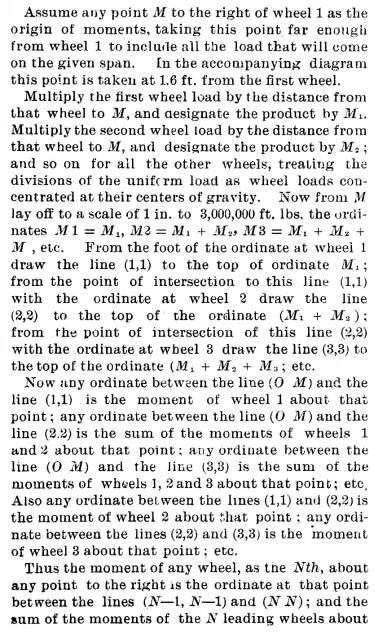
The diagram for any given load may be made in a few moments
on a piece of profile paper as follows:
At the top lay off to a scale of 1-16 in. to 1 ft. the distances
between the wheels, and the distances center to center of gravity
of short lengths of the uniform train load, and draw ordinates
through these points. On these ordinates lay off from the line
(O M) at the bottom of the sheet the sums of the loads up to and
including the load at each ordinate, and draw horizontal lines
from these points to the following ordinates. The stepped line
thus formed may be designated as the load line.
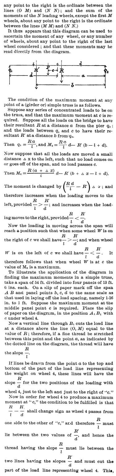
then, is the manner of finding the position of the loading
that will produce a maximum moment at any point of a simple girder
or truss: Place the slip of paper A, B, on which the span
is marked, with the point e, at which the maximum moment
is required, under any assumed wheel, and stretch a fine thread
from a to the point of intersection of a vertical through
B with the load line. If this thread cuts the part of the
load line representing the wheel over c, then the loading
produces a maximum moment at c. If the thread passes above
this part of the load line, move the loading to the left: if it
passes below, move the loading to the right.
It is thus seen that with the use of the load line no arithmetical
work is necessary to ascertain the positions of the loading producing
maximum moments.
Now for the special case above, the assumed position of the
loading with wheel 4 over c produces a maximum moment at
c, since the thread crosses the part of the load line representing
wheel load 4.
Diagram
for Concentrated Rolling Load
Bridge Page
| Contents Page
|


