THE VALUE OF COMPRESSED
AIR IN AND ABOUT RAILROAD SHOPS.
Railway Engineering and Mechanics—November,
1894
BY F. M. TWOMBLY,
Master Mechanic New York, New Haven & Hartford R.R.
The writer, having the supervision of a railway shop that cares
for eighty locomotives making about 210,000 miles per month, also
building all the tanks for 260 locomotives, became Interested
in the use of compressed air and commenced using it In the summer
of 1891, and probably at the present time is using it as extensively
as most any one with a shop of equal size; and he is now prompted
by the numerous inquiries constantly received, to give to the
readers of RAILWAY ENGINEERING
AND MECHANICS, in
a general way, what it is like and what it is worth, as he found
it, without going too much into details.
In applying the numerous devices for the utilization of compressed
air in a shop, much depends upon the way the shop is constructed,
its height, location of machinery, etc.; but more depends upon
the ingenuity of the person making the application, as two shops
cannot be fitted alike, unless they are built and equipped alike.
Those mechanics who are skeptical regarding the utility and economy
of compressed air, the writer would be glad to show his plant;
to those who cannot see it, it will be made as plain as possible
by means of the accompanying illustrations.
With us pneumatic lifts have entirely superseded in the shops
and yard, chain falls, rope falls and blocks, and cranes. So much
has been written about pneumatic lifts that a minute description
of them at this time, is probably not necessary. I will observe,
however, that by the aid of 'seamless tubes, cold rolled steel
for piston rods, leather packing, and cast iron heads bolted together
with rods, their construction is a very simple matter, and inexpensive
in comparison with any other kind of lift. For cylinders 7¾
inches in diameter and less, we use brass; for larger sizes, wrought
iron. To smooth the inside of the latter tubes, a cast iron "slug"
turned a trifle larger than the tube and kept well greased, is
forced through them with hydraulic press. For this idea the writer
is indebted to Mt. J. H. Manning, master mechanic U.P.R.R., Omaha
Neb.
Where the height of a building is insufficient, hoists can
be just as well used horizontally, pulling over a sheave, the
loss by friction, of course, being a little more. In some experiments
made by us, the loss by friction on the direct lift was found
to, be about 3 per cent.
The matter of compressors will not be touched upon in this
article as no opportunity has existed for comparisons, the ordinary
locomotive air pump having been used exclusively; nor have we
made experiments to determine the amount of coal consumed, but
are confident that the amount is a mere ''bagatelle" when
compared with the results obtained and saving made.
 The first lift
constructed was 6 inches in diameter and took the place of a chain
fall used in lifting steel rails into place for dri1ling holes,
which was being done by two men receiving $1.75 and $1.50 respectively,
the change paying more than 300 per cent on the investment. The first lift
constructed was 6 inches in diameter and took the place of a chain
fall used in lifting steel rails into place for dri1ling holes,
which was being done by two men receiving $1.75 and $1.50 respectively,
the change paying more than 300 per cent on the investment.
Air is being used for lifting ashes, made by locomotives, from
the pits to the cars, the apparatus costing less than $200. The
saving over the old method is over $600 per annum, or more than
300 per cent. This is in, constant use every day of the year.
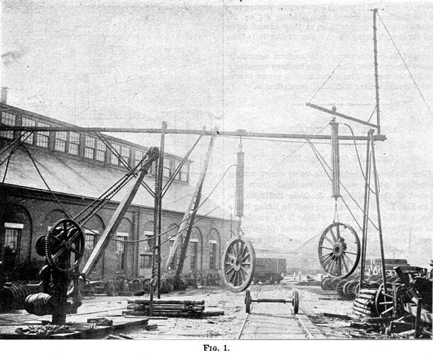
A glance at Fig. 1 will show an overhead railway, constructed
of old rails, a crane, and shears, all operated by air; also an
old crane now obsolete. With the old crane, which is a good one,
five men will use 64 minutes in loading on a car, 16 pair of tender
or car wheels, while with the new crane the same men will do the
work in 10 minutes. While at present there is attached to the
shears only a medium sized cylinder, it is obvious that the size
of the cylinder need only be limited to the strength of the shears.
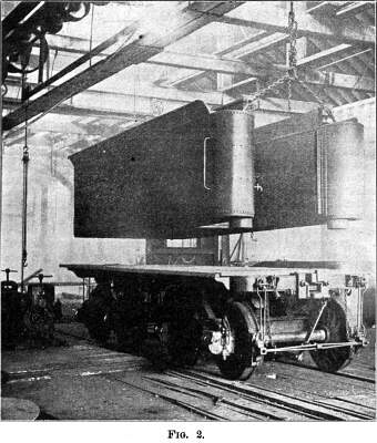
Fig. 2 shows a completed tank, weighing 7,540 lbs., in tank
shop, being raised to place on tender frame. This is accomplished
by two cylinders which lie horizontally on chords of roof, either
of them being capable of raising the load separately. These are
also used for turning tanks over, or, in fact, anything that requires
any pulling.
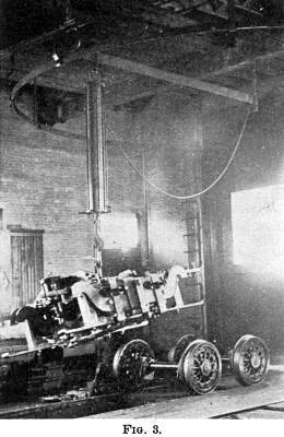 The reader's
attention is particularly called to the overhead arrangement to
which hoist is suspended in Fig. 3. It is a horizontal bar, one
end of which is hung on a spindle or pivot, the other end having
a trolley running on a bar which is an arc of a circle, the pivot
being the center. With the hoist movable on the bar that forms
the radius, it is plain that all of the territory within the sector
can be covered. There are in use in our machine shop about a dozen
of these, ranging from an are of sixty degrees to a full circle. The reader's
attention is particularly called to the overhead arrangement to
which hoist is suspended in Fig. 3. It is a horizontal bar, one
end of which is hung on a spindle or pivot, the other end having
a trolley running on a bar which is an arc of a circle, the pivot
being the center. With the hoist movable on the bar that forms
the radius, it is plain that all of the territory within the sector
can be covered. There are in use in our machine shop about a dozen
of these, ranging from an are of sixty degrees to a full circle.
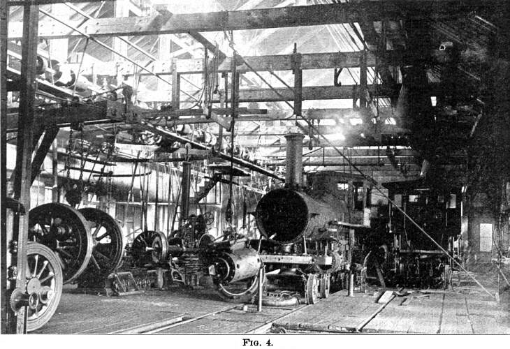
Fig. 4 illustrates how a stationary hoist may be, used to raise
weights at a considerable distance away by means of snatch blocks.
If the bight of the rope, that is seen lifting the cylinder, was
made fast to the "dead man" in floor, and another snatch
block placed in the bight and hooked to the piston, the hoist
would lift half of its capacity through twice its space; we make
considerable use of air in this way. The large driving wheel crane
seen in left of picture, although operated by air, is to be superseded
by overhead railway seen under construction. Immediately back
of cylinder suspended by rope, is a ram coming up through the
floor which is a driving wheel jack, of which we have several,
they being made of old locomotive cylinders. For smaller wheels
we use jacks made of seven inch tender cylinders.
Our bolt cutter is supplied with oil from a reservoir underneath;
constant air pressure is maintained on top of oil, and the flow
is regulated by a cock. Oil after being used is strained into
a pan under the machine and above the reservoir, and when desirable
is conducted back to the reservoir by gravitation, the air being
shut off and a bleeder on the reservoir opened. This arrangement
is better, costs less and is preferable to a pump. The same principle
is used by us in transferring oil from barrels to tanks.
This principle will also be applied to a machine, which we
have under construction, for forcing sand from a reservoir, the
top of which will, be on floor level, to a tank in top of engine
house, from which the sand will be conveyed to sand: boxes of
locomotives the same as water is to tenders. While this machine
is not in operation, experiments have satisfied us that it will
be a success.
We have a pressure gage in the office for registering at all
times, the pressure on, the air plant, and having piped to the
office for this purpose we also operate our letter-copying press
with air.
We have about 300 cubic feet of air storage, about half of
which is in the old boiler. There are many uses that we make of
compressed air not enumerated in this article. Some of them were
mentioned in a former article appearing in RAILWAY
ENGINEER ING AND
MECHANICS for March, 1893.
The writer is decidedly of the opinion that the value of compressed
air in shops cannot well be overestimated.
Build a Locomotive
| Contents Page
|


