THE TESTING OF A LOCOMOTIVE
Scientific American—February 22,
1908
BY FREDERIC BLOUNT WARREN.
Powerful locomotives, no matter how costly, do not matriculate
from the builders' shops into the class that draws the sixteen-hour
trains to Chicago, or pulls the Lake Shore flyers, without first
having demonstrated their capacity by a series of most exacting
tests.
Railroad officials must have some better proof of an engine's
capacity than the mere indorsement of the men who make the mechanism.
So, when locomotives come newly painted and polished from the
big Baldwin shops, for instance, the owners send them into testing
plants, mount them upon a delicate and compact series of registering
instruments, and run them at all speeds, until their weaknesses
have been detected and their strong points emphasized almost to
a fractional degree of an atom. The testing machinery is, in reality,
nothing more than a treadmill, in principle. In outward appearance
it seems to be just so many large wheels revolving on axles, so
arranged that each wheel of the engine under test meets a corresponding
wheel in the tester.
Once in position, an engineer climbs into the locomotive cab,
opens the throttle until it has reached its widest point; the
steam shoots into her tubes and chests, the great wheels begin
to revolve, gain speed and finally become a circling blur, in
which the eye is unable to detect the interstices. Deriving the
full power from its fuel, the forward or backward movement of
the locomotive is nevertheless barely a fraction of an inch.
This is an unromantic testing beside that which Kipling described
with characteristic vigor. The "tryout" which he depicted
consisted of taking an engine, hitching it on to heavy freight
cars and sending it out on the line, on levels and tangents, on
curves and grades, until the machinery demonstrated its worthiness
to take the speedy runs of its owners. Railroad men to-day are
more exacting. Figuratively, their testing plants ask questions
of a mass of wonderfully constructed iron and steel, and the metal
answers them in their entirety.
The chief plant of this kind is located in Altoona, Pa., being
a part of the extensive shop system of the Pennsylvania Railroad.
With a force of sixteen men, it has been in constant operation
since November 19, 1906, and, on an average, about three complete
tests are made each week.
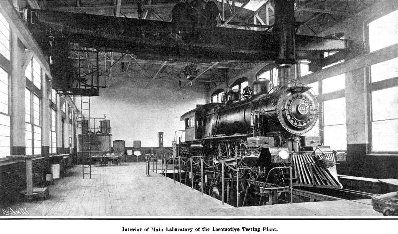
A separate building of steel and brick has been erected for
housing the apparatus. The driving wheels of a locomotive under
test rest upon supporting wheels with rims shaped to correspond
with the head of a rail. The axles of these supporting wheels
carry absorption brakes. The turning of the driving wheels causes
the supporting wheels to revolve, but these are retarded to any
extent desired. The work actually done by the locomotive' consists
in overcoming the friction resistance of the supporting wheels
and brakes, the resulting force exerted at the drawbar being measured
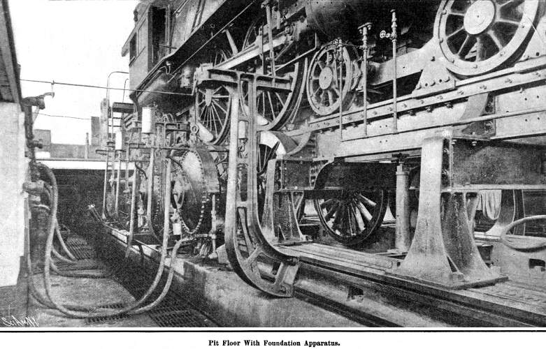
by a traction dynamometer. The axles of the supporting wheels
run in heavy pedestals secured to cast-iron bed-plates resting
upon a concrete foundation. There are two bed-plates running parallel
to the track, and in order that the supporting wheels may be directly
beneath the locomotive drivers, these bed-plates are provided
with T-slots, so that the pedestals may be moved along
parallel to the track, and secured in any position to suit the
particular engine under test. The only wheels of the locomotive
which move during a test are the drivers. The wheels of the leading
truck rest upon rails secured to I-beams and supported
upon the same bed-plates that carry the pedestals. The wheels
of the trailing truck rest upon supporting wheels—which remain
stationary during the test—and are carried by pedestals secured
to longitudinal bed-plates.
Preparation of the testing plant to receive a locomotive consists
of bolting the pedestals to the bed-plates, so spacing them that
there will be a pair of supporting wheels directly beneath each
pair of drivers of the locomotive. A section of special rail is
bolted to the inside faces of the supporting wheels. This rail
is composed of a heavy I-beam, to the top of which is secured
a grooved head in which the flanges of the drivers run. The top
of the supporting wheels are in line with the track entering the
testing plant building, so that a locomotive can be backed in
and the drivers will run on their flanges until in position directly
over their supporting wheels. After a locomotive has been secured
in place and its drawbar attached to a dynamometer, these grooved
rails upon which it ran in are removed, leaving the drivers resting
upon the supporting wheels.
The axle for each pair of supporting wheels carries upon each
of its overhung ends an Alden absorption brake. Each of these
brakes consists of two smooth circular cast-iron disks, keyed
to the supporting-wheel axle. On each side of each one of these
disks is a thin copper diaphragm secured at its periphery, and
also at its inner edge to a housing which does not revolve and
has its bearings upon the hubs of circular revolving disks. The
stationary housing is so designed that when it is filled with
water under pressure the copper disks are forced against the revolving
disks, creating friction. Provision is made for securing continuous
and uniform lubrication of the surfaces of these revolving disks,
and the water is caused to flow through the housing In order to,
carry away the heat generated. Thus the water performs two functions:
it supplies pressure to cause the friction, and it carries away
the heat generated by the friction.
Connection between each brake and the source of water supply
is made by a flexible hose. Discharge pipes for all the brakes
empty into an iron trough, and each pipe is provided with a valve
located adjacent to the valve in the supply pipe for the same
brake. When placing a load upon the locomotive under test, these
valves are adjusted until the individual brakes each absorb their
share of the work. When this preliminary adjustment has been made,
the power absorbed by all of the brakes may be increased or decreased
by operating a large valve in the supply main.
A special system has been installed for the purpose of supplying
water under uniform pressure for use in the brakes.
An adjustable drawbar is used to connect the locomotive with
a dynamometer and, in addition, the dynamometer housing is provided
with a means for raising and lowering the dynamometer proper to
bring this drawbar truly horizontal. Two safety bars are provided
between the locomotive and the dynamometer frame, to decrease
the vibration transmitted to the dynamometer through the drawbar.
At their ends these bars have universal joints to insure perfect
freedom of adjustment, and each bar is provided with an oil dashpot
near the dynamometer end.
The Pennsylvania Railroad's traction dynamometer, which measures
the drawbar pull of the locomotive, is of the lever type. The
weighing mechanism is supported by a frame, which slides up and
down in ways formed by the housings. These housings are very massive,
rigidly secured together, and anchored to a heavy foundation.
The lever system is constructed upon the Emery principle, in which
flexible steel fulcrum plates take the place of knife edges used
in ordinary scales. As the levers are vertical instead of horizontal,
their weight would not come upon the flexible fulcrum plates in
the direction in which they transmit pressure. In certain cases
it has therefore been necessary to supply two fulcrum plates with
their axles at right angles, one for carrying the weight of the
levers, and the other for transmitting the thrust.
The mechanical and mathematical detail entering into this phase
of locomotive testing is so delicate and complicated that it would
be, in an article of this kind, almost wholly unintelligible to
the lay machinist, though of course easily understood by trained
engineering minds.
Of very great interest, however, are the records obtained on
a recording table, over which an endless strip of paper eighteen
inches wide is mechanically drawn, and upon which a continuous
story of the test and its results is told. The paper is driven
by direct connection with one of the supporting wheels of the,
testing mechanism, upon which the locomotive drivers rest. The
speed reduction is so arranged that when the locomotive under
test travels one mile on the supporting wheels, the paper moves
52.8 inches, giving a scale of 100 feet to the inch upon the diagram.
In order to obtain an accurate movement of the paper, it passes
between a finely corrugated brass roller and another roller covered
with rubber. The winding drum to which the paper is finally delivered
is arranged to slip upon its shaft, in order to accommodate its
constantly increasing diameter as the test progresses.
A datum pen marks a continuous straight line upon this paper.
A traction recording pen moves across the paper perpendicular
to the datum line, being dependent upon the force transmitted
by the drawbar from the locomotive. The maximum travel of this
pen away from the datum line is eight inches. Two sets of springs
are provided. With the heaviest set the eight-inch movement of
the traction pen corresponds to a load of 80,000 pounds upon the
drawbar, which represents the maximum capacity of the dynamometer.
With the other set of springs the eight-inch motion of the traction
pen corresponds to a pull of 40,000 pounds upon the drawbar, and
with all the flat springs removed the eight-inch motion corresponds
to a 16,000-pound load. The total motion of the drawbar to give
the eight-inch movement to the recording mechanism is about 0.04
of an inch. The multiplication of the recording and weighing mechanism
is therefore 200 to 1.
An integrator is provided and attached to the traction recording
mechanism, so that the foot-pounds of work performed by the locomotive
is automatically summed up. Five additional electrically-operated
pens are provided. They normally draw continuous straight lines.
One of them is electrically connected to a clock, so that each
second is indicated by a jog in the straight line which the pen
normally draws. Another pen is electrically connected to a roller,
which is, rotated by the recording paper, causing the pen to make
a jog in the line for every thousand feet which the locomotive
travels. Another pen is electrically connected to the integrator,
and makes a jog in its line every time the integrator measures
one square inch. The remaining electrically-operated pens are
used for recording such features of the test as taking indicator
cards.
For handling coal used by the locomotives under test, a very
complete plant has been installed. Bottom-dumping railroad coal
cars are run in on a track beside the test building. They are
dumped into a large hopper, and from this the coal is carried
by a bucket conveyer to two elevated reinforced concrete pockets,
each of which has a capacity of about fifty tons. Each coal pocket
is provided with a hopper cutoff gate at a convenient height above
the main floor of the test building. Coal from the bins, as needed,
is discharged through the gates into wagons holding about 1,000
pounds each, which are run over weighing scales, pushed out to
the locomotive, raised by hydraulic elevator to the firing platform,
and then dumped.
Ashes from the locomotive are discharged at the pit level,
placed in wagons, and removed.
A supply tank located in the corner of the laboratory supplies
the water used in the locomotive boiler. This water first passes
through a meter, the reading of which is used as a check upon
the weighing tanks. A small motor-driven centrifugal pump returns
to the supply tank the overflow from the injectors used on the
locomotive.
So unique and complete is this big testing plant of the Pennsylvania
Railroad, that rarely is there a week that passes when engines
of other railroads are not tested because the owners of the locomotives
lack the facilities in their shops to determine the road value
and capacity of their own transportation haulers.
For the completeness of this plant and the highly-maintained
state of perfection the Pennsylvania officials attribute much
credit to Mr. Theodore N. Ely, Chief of Motive Power of the Lines
East.
Build a Locomotive
| Contents Page
|


