|
CHAPTER XVIII.
THE SHIFTING LINK
EARLY REVERSING MOTIONS.
IN the engineering practice of the world, before the
locomotive and marine engines came into use, there was no need
for devices to make engines rotate in more than one direction.
When the need for a reversible engine first arose, it was met
by very crude appliances. Locomotives were kept at work, earning
money for their owners, which were reversed by the man in charge
stopping the engine, and by means of a wrench changing the position
of the eccentric by hand. A decided improvement on the wrench
was the movable eccentric, which was held in forward or back gear
by stops; the operation of reversing being done by a treadle or
other attachment located near the engineer's position. A serious
objection to this form of reversing gear was, that the abrasion
of work enlarged the slot ends, and wore out the stops, leading
to inaccuracy and frequent breakage. A somewhat better form of
reversing motion was a fixed eccentric, with the means at the
end of the eccentric-rod for engaging with the top or bottom of
a rocker-shaft, which operated the valve-stem. This was the form
of reversing motion used on the early Baldwin engines. Numerous
other appliances, more or less defective, were experimented with
before the double fixed eccentrics were introduced. Till the link
was applied to valve-motion, the double eccentrics—an American
invention—were the most important improvement that had been
made on the locomotive valve-motion since the incipiency of the
engine. The 'V' hook, in connection
with the double eccentrics, made a fair reversing motion in comparison
to any thing that had preceded it. The objection to the hook was,
that, when the necessity arose for reversing the engine while
in motion, much difficulty was experienced in getting the hook
to catch the pin. As a simple, prompt, and certain reversing motion,
the link was readily acknowledged to be far superior to any thing
that had previously been tried.
INVENTION OF THE LINK.
There is no doubt but the link was first applied to
a steam engine by William T. James of New York, a most ingenious
mechanic, who also invented the double eccentrics. James experimented
a great deal about the period from 1830 to 1840, with steam carriages
for common roads; and it was in this connection that he invented
the link. His work having proved a commercial failure, the improvements
on the valve-motion were not recognized at the time; although
the probability is, that Long, who started the Norris Locomotive
Works of Philadelphia, and brought out the double eccentrics upon
the locomotives built there, was indebted to James for the idea
of a separate eccentric for each direction of engine movement.
The credit of inventing the ordinary shifting link is due to
William Howe of Newcastle, England. This inventor was a pattern-maker
in the works of Robert Stephenson & Co., and he invented the
link in 1842 in practically its present form. The idea of Howe
was to get out an improved reversing motion; and he made a pencil-sketch
of the link, to explain his views to his employers. The superintendent
of the works was favorably disposed to the invention, and ordered
Howe to make a pattern of the motion, which was done; and this
was submitted to Stephenson, who approved of the link, and directed
that one should be tried on a locomotive. Although Stephenson
gave Howe the means of applying his invention, he does not seem
to have perceived its actual value, for the link was not patented;
and Stephenson never failed to patent any device which he thought
worth protecting.
The link-motion was applied to a locomotive constructed for
the Midland Railway Company, and proved a success from the day
it was put on. Seeing how satisfactorily the invention worked,
Robert Stephenson paid Howe twenty guineas (one hundred and five
dollars) for the device, and adopted the link as the valve-gear
for his locomotives. This is how the shifting link comes to be
called the "Stephenson link," and the credit for this
invention was not extravagantly paid for.
The capability which the link possesses of varying the steam
admission and release, did not appear to be understood by the
inventor; nor was the mechanical world aware, for some time after
the link was brought into use, that it could be employed to adjust
the inequality of steam distribution, due to the angularity of
the connecting rod.
CONSTRUCTION OF THE SHIFTING LINK.
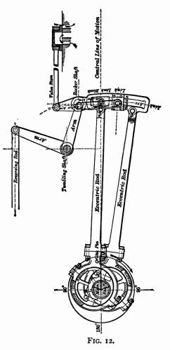 As usually
constructed for American locomotives, the link is a slotted block
curved to the arc of a circle, with a radius about equal to the
distance between the center of the driving-axle and the center
of the rocker-pin. The general plan of the link-motion is shown
in Fig. 12. Fitted to slide in the link-slot is the block which
encircles the rocker-pin. The eccentric-rods are pinned to the
back of the link; the forward eccentric-rod connecting with the
top, and the back-up eccentric-rod with the bottom, of the link.
Bolted to the side and near the middle of the link is the saddle,
which holds the stud to which the hanger is attached; this, in
its turn, connecting with the lifting arm, which is operated by
the reversing rod that enables the engineer to place the link
in any desired position. As usually
constructed for American locomotives, the link is a slotted block
curved to the arc of a circle, with a radius about equal to the
distance between the center of the driving-axle and the center
of the rocker-pin. The general plan of the link-motion is shown
in Fig. 12. Fitted to slide in the link-slot is the block which
encircles the rocker-pin. The eccentric-rods are pinned to the
back of the link; the forward eccentric-rod connecting with the
top, and the back-up eccentric-rod with the bottom, of the link.
Bolted to the side and near the middle of the link is the saddle,
which holds the stud to which the hanger is attached; this, in
its turn, connecting with the lifting arm, which is operated by
the reversing rod that enables the engineer to place the link
in any desired position.
ACTION OF THE LINK.
Regarded in its simplest form, the action of the link in full
gear is the same upon the valve movement as a single eccentric.
When the motion is working, as in the figure, with the eccentric-rod
pin in line with the rocker-pin, it will be perceived that the
movement can not differ much from what it would be were the eccentric-rod
attached to the rocker. Here the forward eccentric appears as
controlling the movement of the valve. Putting the link in back
motion brings the end of the backing eccentric-rod opposite the
rocker-pin, the effect being that the back-up eccentric then operates
the valve. When the link-block is shifted toward the center of
the link, the horizontal travel of the rocker-pin is decreased;
consequently, the travel of the valve is reduced; for, with ordinary
engines, the travel of the valve in full gear equals the throw
of the eccentrics, the top and bottom rocker-arm being of the
same length. The motion transmitted from the eccentrics, and their
means of connection with the link, make the latter swing as if
it were pivoted on a center which had a horizontal movement equal
to the lap and lead of the valve. The extremities of the link,
or rather the points opposite the eccentric-rods, swing a distance
equal to the full throw of the eccentric. The variation of valve-travel
that can be effected by the link, is from that of the eccentric
throw in full gear down to a distance in mid gear which agrees
with the extent of lap and lead. The method of obtaining these
various degrees of travel is by moving the link so that the block
which encircles the rocker-pin shall approach the middle of the
link.
When an engine is run with the lever in the center notch, the
supply of steam is admitted by the lead, opening alone. In full
gear the eccentric, whose rod-end is in line with the rocker-pin,
exerts almost exclusive control over the valve movement; but,
as the link-block gets hooked towards the center, it comes to
some extent under the influence of both eccentrics.
A thoughtful examination of Fig. 12 will throw light on the
reason why the proper position of a slipped eccentric can be determined
by the other eccentric when the engine is on the center. In the
cut, the crank-pin is represented on the forward center; and in
that position the eccentric centers are both an equal distance
in advance of the main shaft center. It will be evident now that
the valve must occupy practically the same position for forward
or back gear, as each of the eccentric-rods reaches the same distance
forward. Putting the motion in back gear would bring the back
up eccentric-rod pin to the position now occupied by the pin belonging
to the forward eccentric-rod.
VALVE-MOTTON OF A FAST PASSENGER LOCOMOTIVE.
Reducing the travel of the valve by drawing the reverse-lever
towards the center of the quadrant, and consequently the link-block
towards the middle of the link-slot, not only hastens the steam
cut-off, but it accelerates in a like degree every other event
of steam distribution throughout the stroke. To explain this point,
let us take the motion of a well-designed engine in actual service,
which has done good economical work on fast train running. The
valve-travel is five inches, lap one inch, no inside lap, lead
in full gear z inch, point
of suspension b inch back of
center of link.
EFFECT OF CHANGING VALVE-TRAVEL.
When this engine is working in full gear, the steam
will be freely admitted behind the piston till about eighteen
inches of the stroke, when cut-off takes place; and the release
or exhaust opening will begin at about twenty-two inches of the
stroke, giving four inches for expansion of steam. Now, if the
links of this engine are hooked up so that the cut-off takes place
at six inches of the stroke, the steam will be released at sixteen
inches of the stroke; and at that point compression will begin
at the other end of the cylinder.
WEAK POINTS OF THE LINK-MOTION.
This attribute which the link-motion possesses, of
accelerating the release and compression along with the cut-off,
is very detrimental to the economical operating of locomotives
that run slow. High-speed engines need the pre-release to give
time for the escape of the steam before the beginning of the return
stroke; and the compression is economically utilized in receiving
the heavy blow from the fast-moving, reciprocating parts, whose
direction of motion has to be suddenly changed at the end of each
stroke, and in helping to raise the pressure promptly in the cylinder
at the beginning of the stroke. A locomotive, on the other hand,
that does most of its work with a low-piston speed, would not
suffer from back pressure if the steam were permitted to follow
the piston close to the end of the stroke; and a very short period
of compression would suffice. If the engine, whose motion we have
been considering, instead of releasing at sixteen inches, could
allow the steam to follow the piston to twenty-two inches of the
stroke, after cutting off at six inches, a very substantial gain
of power would ensue. And this would be well supplemented by avoiding
loss of power, did compression not begin till within two inches
of the return stroke.
WHY DECREASING THE VALVE-TRAVEL INCREASES
THE PERIOD OF EXPANSION.
Increase of expansion follows reduced valve-travel,
from a similar cause to that which produces expansion when lap
is added to the edge of a slide-valve. When the valve is made
with the face merely long enough to cover the steam-ports, there
can be no expansion of the steam; for, so soon as the valve ceases
to admit steam, it opens the steam-port to the exhaust. When lap
is added, however, the steam is inclosed in the cylinder, without
egress for the time that it takes the lap to travel over the steam-port.
An arrangement of motion which will make the valve travel quickly
over the port, has a tendency to shorten the period for expansion;
while making the valve travel slowly over the port, has the opposite
effect, and protracts expansion. A valve with, say, five inches
travel, has a comparatively long journey to make during the stroke
of the piston; and the lap-edges will pass quickly over the steam-ports—much
more quickly than they will when the travel is reduced to three
inches. In a case of this kind, there is more than the mere reduction
of travel to be considered. Suppose the valve has one inch lap
at each end. When it stands on the middle of the seat, it has
a reciprocating motion of two and one-half inches at each side
of that point to make. At the beginning of the stroke, it has
been drawn aside one inch (we will ignore the lead), but still
has one and one-half inch to travel before it begins to return.
On the other hand, when the travel is reduced to three inches,
the valve has only one and one-half inch to travel away from the
center; and, one inch being moved to draw the lap over the port,
there only remains one-half inch for the valve to move before
it must begin returning. This entails an early cut-off; for the
valve must pass over the ports with its slow motion, and be ready
to open the port on the other end, before the return stroke. Thus
a travel of five inches draws the outside edge of the valve one
and one-half inch away from the outside of the steam-ports, three
inches travel only draws it one-half inch away, and a greater
reduction of travel decreases the opening in like proportion.
INFLUENCE OF ECCENTRIC THROW ON THE VALVE.
As reducing the travel of the valve diminishes the
port opening, a point is reached in cutting off early in the stroke
where the port opening is hardly any more than the port opening
due to the lead. This is what makes long steam-ports essential
for a successful high-speed locomotive. The best-designed engines
give an exceedingly limited port opening at short cut-offs, and
badly planned motion sometimes seriously detracts from the efficiency
of the engine, by curtailing the opening at the point where a
very brief time is given for the admission of steam. The magnitude
of the eccentric throw exerts a direct influence on the port opening
when cutting off early. A long throw tends to increase the opening,
while a short throw reduces it. The long-throw eccentric will
draw the valve farther away from the edge of the steam-port, when
admitting steam for the same point of cut-off, than a short-throw
eccentric will move its valve. For an ordinary 17 X 24 inch locomotive,
the throw of eccentric should not be less than five inches, unless
the engine is intended entirely for slow running. There are many
engines running with eccentric throw less than five inches, but
they are invariably slow unless the valve-lap is very short. With
an ordinary lap, an engine having an eccentric throw of 42 inches needs so much angular advance
to overcome the lap, and provide lead, that the rectilineal motion
of the eccentric is very meager at the beginning of the stroke.
That is, the center of the eccentric is traveling downward in
its circular path, which gives little motion to the valve, just
as the crank gives decreased motion to the cross-head when near
the centers.
HARMONY OF WORKING-PARTS.
Hitherto we have regarded the link as merely performing
the functions of transmitting the motion of the eccentrics to
the valves, with the additional capability of reducing the travel
at the will of the engineer. Otherwise, the motion of the link
is intensely complex; and its movements are susceptible to a multitude
of influences, which improve or disturb its action on the valve.
A good valve-motion is planned according to certain dimensions
of all the working-parts; and any change in their arrangement
will almost invariably entail irregularities upon the link's movement,
which will radically affect the distribution of steam. A link-motion
schemed for an eccentric throw of 42
inches will not work properly if the throw be increased
to five inches: a link with a radius of 57 inches can not be changed
with impunity for one of 60 inches. Any change in the position
of the tumbling-shaft or rocker-arms distorts the whole motion,
and any alteration in the length of the rods or hangers has a
similar effect. That the link may perform its functions properly,
all its connections must remain in harmony.
ADJUSTMENT OF LINK.
A very important feature of the link is its property
of adjustability, which serves to neutralize the distorting effect
of the connecting rod's angularity. As has already been explained,
the angularity of the main rod tends to delay the cut-off during
the backward stroke, while it is accelerated in the forward stroke.
With the ordinary length of connections, this irregularity would
seriously affect the working of the engine. But it is almost entirely
overcome by the link, which can be suspended in a way that will
produce equality for the period of admission and point of cut-off
for both strokes in one gear. Perfect equalization of admission
and cutoff for both gears has been found impossible with the link-motion;
and designers are generally satisfied to adjust the forward motion,
and permit the back motion to remain untrue. The point about the
link which exercises the most potent influence on adjusting the
cut-off, is the position of the saddle, or of its stud for connecting
the hanger. This stud is called the point of suspension. Raising
the saddle away from the center of the link will effect adjustment
of steam admission; but in locomotive practice the saddle is nearly
always located in the middle of the link, there being practical
objections against raising it. Equalization of steam distribution
is produced by placing the hanger-stud or point of suspension
some distance back of the center line of the link-slot, the distance
varying from 8 inch to d inch.
Moving the hanger-stud affects the link's movement in a way
that is equivalent to temporarily lengthening the eccentric-rod
during a portion of the piston-stroke. The length of the tumbling-shaft
arms, the length of hanger, the location of the rockers and tumbling-shaft,
the radius of link, and length of rods, all exercise influence
on the accurate adjustment of the valve-motion.
SLIP OF THE LINK.
In equalizing the valve-motion, and overcoming the
discrepancy of steam admission, due to the angularity of the connecting
rod by moving the link-hanger stud away from the center of the
slot, a new distortion is introduced. The link-block being securely
fastened to the bottom of the rocker-pin, moves in the fixed arc
traversed by that pin, which is nearly horizontal. The action
of the eccentric-rods on the link, on the other hand, forces the
latter to move with a sort of vertical motion at certain parts
of the stroke, making it slip on the block. Moving the hanger-stud
back tends to increase this slip, which will become excessive
enough to seriously impair the efficiency of the motion if not
kept within bounds by the designer. Where the slip is very great,
the motion will not be serviceable, a consideration which can
never be overlooked; for the block will wear rapidly, producing
lost motion, a very undesirable defect about any part of a link-gear.
With the long rods which prevail in locomotive practice, designers
have no difficulty in keeping the slip within practical bounds;
but with marine engines it is sometimes necessary to sacrifice
equality of steam admission to the reduction of the slip. The
greatest amount of slip is in full gear, and it diminishes as
the link-block is moved towards the center.
Placing the eccentric-rod pins back of the link-arc, as is
almost universally done in this country, has a tendency to make
the link slip on the block; and care has to be taken not to locate
these pins farther back than is actually necessary for other requirements
of the link-motion's adjustment. Auchincloss, who is a recognized
authority for designing of link-motion, gives four varieties of
alterations capable of reducing the slip when it is found too
great for a practicable motion.
His resorts are, either to increase the angular advance, reduce
the travel, increase the length of link, or shorten the eccentric-rods.
One, or a combination, of these methods may be adopted, as the
designer finds most convenient.
RADIUS OF LINK.
Among the constructing engineers who plan link-motion,
there is considerable diversity of opinion about what radius of
link helps to produce the best valve-motion. The distance between
the center of axle and center of lower rocker-pin may be accepted
as, approximately correct, although some designers slightly increase
beyond these points. On the other hand, the locomotives sent out
from a leading building establishment have the radius of link
drawn w inch per foot short
of the distance between the axle and rocker; and the claim has
been made, that the arrangement produces an excellent motion.
A committee of the American Master Mechanics' Association have
placed themselves on record on this subject by asserting that
the distance between the centers of axle and rocker-pin is the
proper radius for the link. That same committee recommended that
the link-motion should be planned to give as long a link radius
as possible, subject to the first-mentioned conditions.
It must be noted that the middle of the link-slot is the radius
arc. I knew of a case where the links for an altered locomotive
were finished out of the true radius through the edge of the slot
being taken as the radius-curve.
INCREASE OF LEAD.
Most of the men who are at all familiar with the valve-motion
are aware of the fact, that, with the shifting link, the lead
increases as the link is notched towards the center. Where the
valve has z inch lead in full
gear, it is no unusual thing to find it increase to a
inch lead opening at mid gear. The phenomenon is better known
than its cause is understood.
The relative positions of link and eccentric centers of an
engine, when the crank is on the forward center, are shown in
Fig 13; 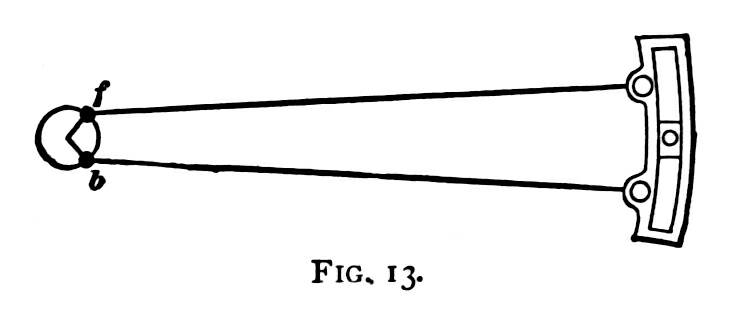
the link being represented with the block in the center, which
represents mid gear. It will be observed that the centers of the
eccentrics f and b, from which the rods receive
direct influence, are both some distance ahead of the center of
the axle, the one above, the other below. The eccentric-straps
to which the rods are connected sweep round the eccentric circles,
and are controlled thereby. When the link is moved up or down,
each eccentric-rod pin, where it attaches to the link, describes
the arc of a circle with a radius drawn from its own eccentric.
If both rods were worked with a radius from the axle-center, the
link could be raised and lowered when the engine stands on the
dead center, without moving the rocker pins at all; but, under
the existing arrangement, the link is influenced directly by one
or other of the eccentrics, whatever position in the link the
block may stand. When the engine is standing on the forward center,
with the link in mid gear, as shown in Fig. 13, it will be readily
perceived that the block stands at its farthest point away from
the axle; for the rods are so placed to reach their greatest horizontal
distance ahead, and consequently in this position the lead opening
is greatest. If the link be now lowered, the backing eccentric-rod
will immediately begin to pull the link back: and, as the pin
of the forward eccentric-rod approaches the central line of motion,
it will also keep drawing the link back; so that, by the time
the link is in full gear, the lead opening will be considerably
reduced.
When the engine stands on the back dead center, as shown in
Fig. 14, the eccentric centers will be on the other side of the
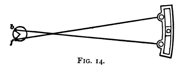 axle, and the
eccentric-rods will be crossed. While in mid gear, the link-block
is drawn closer to the axle than it would be in any other position
of the link; and consequently the lead opening is greatest. If
the link be now lowered, the forward eccentric-rod will approach
its horizontal position, and consequently reaches farther on the
central line of motion, so it will push the link-block away from
the axle, thereby decreasing the lead. Pulling the link into back
gear has a similar effect. axle, and the
eccentric-rods will be crossed. While in mid gear, the link-block
is drawn closer to the axle than it would be in any other position
of the link; and consequently the lead opening is greatest. If
the link be now lowered, the forward eccentric-rod will approach
its horizontal position, and consequently reaches farther on the
central line of motion, so it will push the link-block away from
the axle, thereby decreasing the lead. Pulling the link into back
gear has a similar effect.
The tendency of a link-motion to increase the lead towards
the center is made greater by shortening the eccentric-rods. Increasing
the throw of eccentric inclines to accelerate the lead towards
the center, since it throws the eccentric centers farther apart.
For slow running, hard-pulling locomotives, where increase of
lead is a disadvantage, the tendency to increase the lead is sometimes
restrained in forward gear by reducing the angular advance of
the backing eccentric. This expedient is, however, not necessary
where proper care and intelligence have been bestowed in the original
design of the motion.
In studying this part of the valve-motion, a young machinist
or engineer will obtain valuable assistance by cutting a link
template out of a piece of pasteboard, and using strips of wood
as eccentric-rods. With these he can test on a drawing-board or
table the various positions of the link, and note, in a way that
is easily understood, the effect of changing the link into different
positions.
Table of Contents
| Contents Page
|


