|
CHAPTER XX.
By -. G. A. Aleyer.
LAYING OUT LINK-MOTION.
FIG. 19 is an outline of a link-motion such as is generally
applied to the American locomotive. It can be adjusted to control
the movement of the slide-valve in such a manner that equal portions
of steam will be admitted alternately at each end of the cylinder.
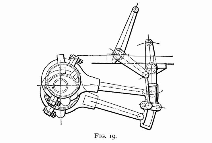
In the following article we propose to explain how this can be
accomplished.
Although we would not advise any person to be satisfied with
approximate rules or constructions, yet cases do occur where the
approximate constructions, being so very near correct, on account
of their simplicity, are of greater practical value than the application
of the rigid and more difficult theoretical rules.
By these remarks, we do not wish the reader to understand that
the following constructions are all done according to the rules
of thumb — not by any means; for all, with the exception
of a few points, are theoretically correct. At the end of this
article, we will point out those points which are, and which are
not, approximately found; so that the reader may feel satisfied
that our construction may always be relied upon as being correct
for all practical purposes.
In what follows, the cylinder will always be regarded as lying
on the right-hand side of the axle, the link being between cylinder
and axle, and the axle located in the center of pedestal.
To avoid any misunderstanding, we will explain the meaning
of some of the terms used.
The length of crank is the distance from center of axle to
center of crank-pin.
For convenience, we shall call the total distance from center
of eccentric-strap to the center of eccentric-pin in the link
the length of the eccentric-rod.
The throw of eccentric is double the distance from center of
axle to center of eccentric-wheel.
The length of the connecting rod is the distance from the center
of crank-pin hole to center of cross-head pin-hole.
The length of link-hanger is the distance from center to center
of holes.
CONDITIONS.
Since this article treats only on the adjustment of the link-motion,
the following items are supposed to be known and established:
The lap of valve, which in this case will be three-fourths of
an inch; the throw of eccentrics, 5 inches; the stroke of the
piston, 24 inches; the position of the rocker, as per Fig. 19;
the length of the rocker-arms, which are in this case of equal
length; length of link-hanger and all dimensions of link, complete,
as shown in Fig. 19 and also the length of the connecting rod.
The adjustment of the link-motion may at first sight appear to
be a difficult problem, as we must have a knowledge of the relative
motions of the piston and slide-valve; but by reducing this problem
to several elementary problems, so that the laws governing the
relative motions may be discovered and clearly defined, a clear
conception of our subject can be gained, and the solution of our
original problem can be accomplished with comparative ease.
In order to find what kind of elementary problems are applicable,
let us suppose that we are looking at a locomotive with a link-motion,
as shown in Fig. 19, applied and correctly adjusted. Now let us
examine it, commencing with the valve. We find that the valve
receives its motion from the upper rocker-arm, and this receives
its motion from the lower rocker-arm. According to our conditions,
previously stated, both of the rocker-arms are of the same length;
and, therefore, the arc described by the upper rocker-arm will
be the same length as the arc described by the lower one. We also
notice that the link which moves the lower rocker-arm is held
in position by the lifting-shaft arm. The question, then, will
naturally arise, Must this lifting-shaft arm have some particular
length, and the center of lifting-shaft have some particular position?
We answer, "Yes;" and this is one of our elementary
problems to solve. Again, we notice that the saddle-pin is not
in the center of the link; and we ask again, "Why?"
To answer this will be another elementary problem. The next we
notice are our eccentric-rods. These we find, on examination,
to have some particular length; and to find this length is another
elementary problem. Next we examine our eccentrics: these, we
find, are fastened to the axle; and, since the crank is also fastened
to the same axle, it follows that there are some relative positions
between them; to find these positions is another elementary problem.
Now let us look once more at the rocker, and we find that the
two rocker-arms are not in the same straight line: hence, to find
the amount of offset is another elementary problem. And, lastly,
we must be able to find the position of crank-pin to correspond
with the position of piston when at full stroke at either end
of the cylinder, and also when at half stroke moving in either
direction.
Here, then, we have all the elementary problems that are necessary
to be understood for the solution of our original problem.
We will now explain all these problems, in an order the reverse
to that in which we stated them: hence we have the following order
—
1st, To find position of crank at full and half stroke.
2d, To find center line of motion, and amount of offset in
rocker-arms.
3d, To find relative positions of crank-pin and eccentrics
when at full and half stroke.
4th, To determine the correct length of eccentric-rods.
5th, To find position of saddle-pin.
6th, To find the position of the center of lifting-shaft and
length of arms.
PROBLEM 1, FIGS. 20 and 21.—To find the position of
crank when the piston is at full and half stroke.— Let
the center of wheel and the axis of the cylinder be in the same
straight line as AD, Fig. 20. With any point C as
a center, and a 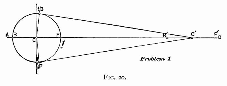 radius
equal to the length of the crank, describe a circle F,
2F, B, 2B;
and let us call this the crank-pin circle. The straight line
AD intersects the circumference of the circle in the points
F and B. The point F will be the center
of crank-pin when piston is at full stroke at the forward end
of the cylinder, and point B will be the center of crank-pin
when the piston is at full stroke at the rear end of the cylinder.
With the point F as a center, and with a radius
equal to the length of the connecting rod, describe an arc intersecting
the line AD in the point F'; with the point B
as a center, and with the same radius, describe an arc intersecting
the straight line AD in the point B'; and with the
point C as a center, and with the same radius, describe
an arc intersecting the straight line AD in the point C.
Point F' will be the center of cross-head pin when the
center of crank-pin is at F, and B' the center of
cross-head pin when the crank-pin is at B, and the point
C' will be the position of center of cross-head pin when
piston is at half stroke. With point C' as a center, and
a radius equal to the length of the connecting rod, describe an
arc passing through the point C, and intersecting the crank-pin
circle in the points 2F
and 2B: these points
will be the position of crank-pin when the piston is at half stroke,
or when the center of cross-head pin is at C'. radius
equal to the length of the crank, describe a circle F,
2F, B, 2B;
and let us call this the crank-pin circle. The straight line
AD intersects the circumference of the circle in the points
F and B. The point F will be the center
of crank-pin when piston is at full stroke at the forward end
of the cylinder, and point B will be the center of crank-pin
when the piston is at full stroke at the rear end of the cylinder.
With the point F as a center, and with a radius
equal to the length of the connecting rod, describe an arc intersecting
the line AD in the point F'; with the point B
as a center, and with the same radius, describe an arc intersecting
the straight line AD in the point B'; and with the
point C as a center, and with the same radius, describe
an arc intersecting the straight line AD in the point C.
Point F' will be the center of cross-head pin when the
center of crank-pin is at F, and B' the center of
cross-head pin when the crank-pin is at B, and the point
C' will be the position of center of cross-head pin when
piston is at half stroke. With point C' as a center, and
a radius equal to the length of the connecting rod, describe an
arc passing through the point C, and intersecting the crank-pin
circle in the points 2F
and 2B: these points
will be the position of crank-pin when the piston is at half stroke,
or when the center of cross-head pin is at C'.
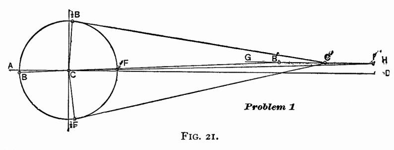 It often happens
that the axis of the cylinder is above the center of axle. When
such is the case, we must follow the construction as shown in
Fig. 21. Let two inches be the distance that the center of axis
of cylinder is above the center of axle. It often happens
that the axis of the cylinder is above the center of axle. When
such is the case, we must follow the construction as shown in
Fig. 21. Let two inches be the distance that the center of axis
of cylinder is above the center of axle.
Draw a straight line AD through the center of axle C;
two inches above this draw a straight line GH parallel
to AD; this line will then pass through the axis of cylinder.
With the center of axle C on the straight line AD as
a center, and a radius equal to the length of the crank, describe
a circle F, 2F, B,
2B: this circle
will be the crank-pin circle. With the point C as a center,
and a radius equal to the length of the connecting rod plus the
length of the crank, describe an arc intersecting the straight
line GH in the point F': this point will be the
position of the cross-head pin when the piston is at full stroke
forward. Through the points F' and C draw a straight
line, intersecting the crank-pin circle in the point F: this
point will be the position of the center of the crank-pin when
the piston is at full stroke forward. Again, with the point C
as a center, and a radius equal to the length of, the connecting
rod minus the length of the crank, describe an arc intersecting
the straight line GH in the point B': this point
will be the position of the center of the cross-head pin when
the piston is at full stroke in the rear end of the cylinder.
Through the points B and C draw a straight line,
intersecting the crank-pin circle in the point B: this
point will be the position of the center of crank-pin when the
piston is at full stroke in the rear end of the cylinder. Find
a point C' exactly central between the points B' and
F' on the line GH: in other words, bisect the distance
B' F' by the point C'. With the point C' as a center,
and a radius equal to the length of the connecting rod, describe
an arc intersecting the crank-pin circle in the points 2B
and ½F: these two points will be the center of crank-pin
when the piston stands at half stroke. In the link-motion, as
shown in Fig. 19 the axis of the cylinder is supposed to be 2
inches higher than the center of axle. For this reason the construction
shown in Fig. 21 will hereafter be used.
PROBLEM 2, FIG. 22. — To find the center line of motion
and the amount of offset in the lower rocker-arm. — Let
C be the centre of axle: through C draw the straight
lines AD and KL perpendicular to AD. The
center of rocker we find in Fig. 19 to be 372
inches in front of the center of axle, and 72
inches above. We therefore continue our construction in Fig. 22
by drawing a straight line MN 372
inches in front of, and parallel to, the straight line KL,
and another straight line OP parallel to AD, and
72 inches above it. These two
lines intersect in the point Q, and this point is the center
of rocker. With Q as a center, and a radius equal to the
length of the lower rocker-arm, describe the arc RS: through
the point C draw a straight line CT tangent to the
arc RS, then CT will be the center line of motion.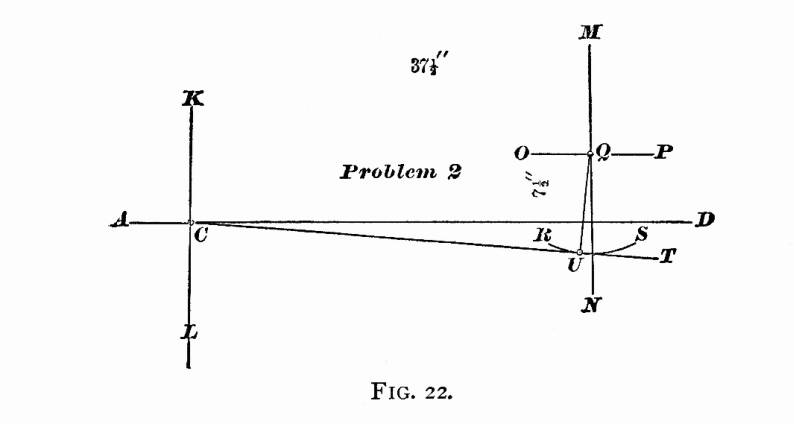 To find the amount
of offset in the lower rocker-arm, let us place the center line
of the upper rocker-arm perpendicular to a line drawn parallel
to the valve surface: but in our case this valve surface is parallel
to the line AD; hence our line drawn parallel to the valve
surface will also be parallel to the line AD, and the center
line of upper rocker-arm will be perpendicular to AD, and
coincide with the line MN. Through the point Q draw
a straight line perpendicular to the line CT, and intersecting
the arc RS in the point U: then the distance from
the point U to the line MN will be the amount of
the offset in the lower rocker-arm. To find the amount
of offset in the lower rocker-arm, let us place the center line
of the upper rocker-arm perpendicular to a line drawn parallel
to the valve surface: but in our case this valve surface is parallel
to the line AD; hence our line drawn parallel to the valve
surface will also be parallel to the line AD, and the center
line of upper rocker-arm will be perpendicular to AD, and
coincide with the line MN. Through the point Q draw
a straight line perpendicular to the line CT, and intersecting
the arc RS in the point U: then the distance from
the point U to the line MN will be the amount of
the offset in the lower rocker-arm.
PROBLEM 3, FIG. 23. — To find the relative positions
of crank-pin and eccentrics when the piston is at full and half
stroke. — Let C be the center of axle. Through
C draw the horizontal line AD, and find the positions
of center of crank-pin at 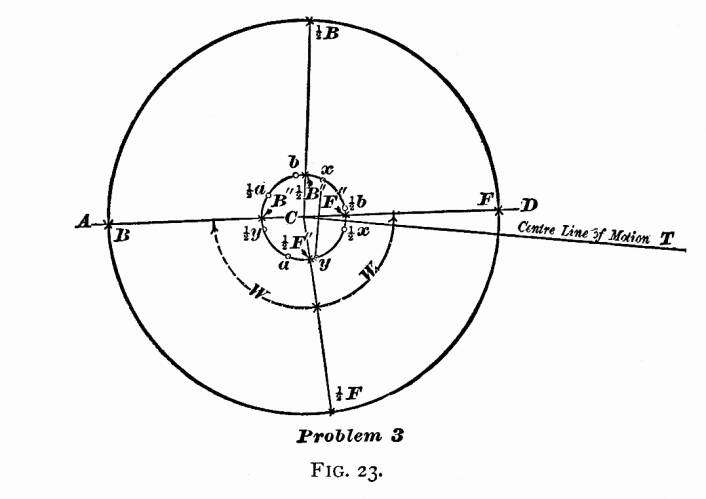
full and half stroke; namely, the points F, 2F,
2B, B as explained
in Problem 1 and shown in Fig. 21. Next draw the center line of
motion as explained in Problem 2 and Fig. 22. With the point C
as a center, and a radius equal to 2
the throw of the eccentric (22
inches), draw a circle; and let us call this circle the "eccentric-circle."
On the line of motion CT, lay off a point towards the rocker
M of an inch from C
(this being the sum of the lap and lead,— w
of an inch for the lap, and z
of an inch for the lead) through this point draw a straight line
perpendicular to the line of motion CT, and intersecting
the eccentric-circle in the points x and y. The
point x will be the center of the forward eccentric; and
the point y will be the center of backward eccentric when
the center of crank-pin is at F, full stroke forward. Through
the points F and C draw a straight line, intersecting
the eccentric-circle in the point F". The line FC
will represent the center line of crank; and the distance between
the points F" and x, measured on the eccentric-circle,
is the amount that the center of forward eccentric is set back
of the center line of crank; and the distance between the points
F" and y is the amount that the backward eccentric
is set ahead of the center line of crank. Since both the crank
and eccentrics are fastened to the same axle, it follows, that,
whatever position the center line of crank may be in, the distances
between center line of crank and eccentrics — that is, the
distances between F'' and x, also F"
and y, measured on the eccentric-circle—remain constant.
Therefore, to find the position of eccentrics when the crank stands
at 2F (half stroke),
draw the straight line 2 FC
representing the center line of crank, and intersecting the eccentric-circle
in the point 2F". From
the point 2F", lay
off on the eccentric-circle a point with a distance equal to F"
x, back of the center line of crank, and indicate this point
by 2x; also from 2F" measured on the
same circle, lay off a point in the front of the center line of
crank, and with a distance equal to F" y and mark
this point 2y; then
the point 2x will be
the position of forward eccentric, and the point 2y
will be the position of backward eccentric when the crank-pin
is at 2F. In precisely
the same manner we find the position of eccentrics when the center
of crank-pin is at B (full stroke back). Through the points
C and B draw a straight line, intersecting the eccentric-circle
in the point B". From the point B", and
with a distance equal to F" x lay off a point on the
eccentric-circle back of crank; this point will be the position
of forward eccentric when crank is at full stroke back; and, in
order to distinguish this from the other position of eccentric,
call this point a: also from B", lay off in front
of the crank the position of backward eccentric at a distance
equal to F" y and call this point b. In the
same manner find points 2a
and 2b when the crank-pin
is at 2B. We have now
found the position of eccentrics when the crank-pin stands in
the following positions:—
Full stroke forward F, the forward eccentric will be
at x.
Half stroke forward ½F, the forward eccentric
will be at 2x.
Full stroke back end B, the forward eccentric will
be at a.
Half stroke back end 2B,
the forward eccentric will be at 2a.
Full stroke forward F, the backward eccentric will
be at y.
Half stroke forward ½F, the backward eccentric
will be at 2y.
Full stroke back end B, the backward eccentric will
be at b.
Half stroke back end 2B
the backward eccentric will be at 2b.
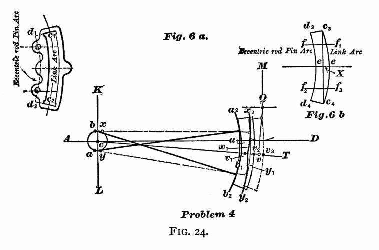 PROBLEM 4,
FIG. 24. — To determine the correct length of the
eccentric-rods. — Let c be the center of axle.
Through this point draw the horizontal line AD, also a
line KL perpendicular to AD. The only purpose for
which these two lines are drawn in this problem, as well as the
others, is to have some lines from which we can locate other lines
or points. Locate the center of rocker, and center lines of rocker-arms,
as explained in Problem 2, and shown in Fig. 22; the lower arm
standing perpendicular to the center line of motion, and the upper
arm vertical. When the arms stand in this position, the rocker-pins
will move through an equal distance on each side of these center
lines during the time that the valve is making its full travel. PROBLEM 4,
FIG. 24. — To determine the correct length of the
eccentric-rods. — Let c be the center of axle.
Through this point draw the horizontal line AD, also a
line KL perpendicular to AD. The only purpose for
which these two lines are drawn in this problem, as well as the
others, is to have some lines from which we can locate other lines
or points. Locate the center of rocker, and center lines of rocker-arms,
as explained in Problem 2, and shown in Fig. 22; the lower arm
standing perpendicular to the center line of motion, and the upper
arm vertical. When the arms stand in this position, the rocker-pins
will move through an equal distance on each side of these center
lines during the time that the valve is making its full travel.
Next find centers of eccentrics x and y when
the crank is at full stroke forward; also a and b
when the crank is at full stroke back, as explained in Problem
3, and shown in Fig. 23. Before we proceed, let us give names
to some of the lines, as shown in Fig. 6a. The arc c1
c2 drawn through the center of opening of the
link, we will call the link-arc; and the arc d1
d2 drawn through the center of eccentric-rod
pin-holes, we will call the eccentric-rod pin-arc. Both of these
arcs are drawn from the same center; that is, the center from
which the link is drawn. Let us now cut a paper template, as shown
in Fig. 6b (link structure). This template is cut so that,
if it is laid on the link, Fig. 6a, the arc of the template
c3 c4 will coincide with the
link-arc c1 c2 and d3
d4 with the eccentric-pin arc d1
d2 the end of template d3 c3
with the line d1 c1, and the
end d4 c4 with d2
c2. On this template join the points c3
c4 by a straight line, and bisect this line
by the perpendicular line ee: on this line the center of
the saddle-pin will be located. On one side of this line draw
the line ff1 parallel to ee, and on the
other side draw f2 f3 also
parallel to ee; the distance from the point f to
the point f2 being equal to the distance between
the centers of eccentric-rod pins, and f e equal to e
f2. The points f and f2
on the arc d3 d4 indicate the position
on the template of the centers of eccentric-rod pins. On the center
line of motion c T, lay off from v a point
v1 towards the axle, with a distance equal to
c1 d1, Fig. 6a; then
with the point x as a center, and cv1
as a radius, describe the arc x1 x2;
in this arc the upper eccentric-rod will be located as long as
the center of forward eccentric remains at x. With the
point y as a center, and cv1 as a radius,
describe the arc y1 y2: in
this arc the center of lower eccentric-rod will be located as
long as the backward eccentric remains at y. With the point
a as a center, and cv1 as a radius, describe
an arc a1 a2: in this arc
the upper eccentric-rod pin will be located while the forward
eccentric is at a. With the point b as a center,
and cv1 as a radius, describe the arc b1
b2; and in this arc the center of lower eccentric-rod
pin will be located when the backward eccentric is at b. Now
adjust the template on the drawing so that the point f will
be in the arc x1 x2: point
f2 in the arc y1 y2
and the line ee coincide with the center line of motion
c T. Along the arc c3 c4
of the template draw an arc on the paper. Next move the template
so that the point f will be in the arc a1
a2, the point f2 in the arc
b1 b2 and the line
ee coincide with the center line of motion c T,
and along the arc c3 c4 of
the template draw the second arc on the paper. Now, if the distance
measured on the arc RS from the point v (the center
of the lower rocker-arm pin) to the first arc drawn, is equal
to the distance measured on the arc RS from v to
the second arc, the radius cv1 will be the correct
length of the eccentric-rods. But, if the distance from v
to the first arc is less than the distance from v to the
second arc, the length cv1 of the eccentric-rod
will be too short. In this case we must increase the length cv1
by adding an amount equal to one-half the difference of the distances
from v to the first arc, and from v to the second
arc previously drawn; and this last length so found will be the
correct length of eccentric-rods.
It will be proper to remark here, that the radius cv1
was assumed to be the correct length of eccentric-rods; but since
the rods cross each other when the eccentrics are at a
and b, and do not cross each other when at x and
y, the radius cv1 will always be a trifle
short. It is therefore necessary to make the correction as explained.
In every case, the length of eccentric-rods must be so adjusted,
that, when the line ee coincides with the center line of
motion cT, the arc vv2 (which is the
amount that the rocker-pin is drawn towards the axle from the
line Qv when the eccentrics are at a and b)
must be equal to the arc vv3 (which is the amount
that the rocker-pin is moved towards the cylinders from the line
Qv when the eccentrics are at x and y); the
straight line Qv being perpendicular to the center line
of motion cT.
PROBLEM 5, FIG. 25. — To find the position of the center
of saddle-pin. — For this problem we again call to our
aid the paper template shown in Fig. 6b. We have already
seen in Problem 4 that the center of saddle-pin will be located
on the line ee drawn on this template: it now only remains
to determine the distance of this point from the link-arc c3
c4.
Since the inequality between the crank-angle W and W1,
Fig. 23, becomes the greatest when the crank stands at half stroke,
it is of the utmost importance to find such a position for the
center of saddle-pin that equal portions of steam will be admitted
alternately when the crank stands at half stroke. Or, in other
words, the admittance of steam must cease at the moment that the
piston has completed one-half stroke.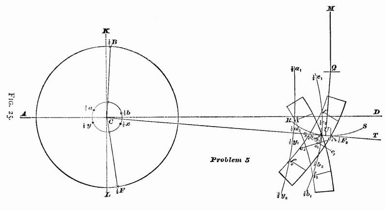 Let us commence this problem as we began the others;
namely, Through the center of axle C, Fig. 25, draw the
horizontal line AD, also the vertical line LK. Find
the position of crank at half stroke, as shown in Fig. 21.
Next find the position of center line of motion CT,
and position of rocker, as shown in Fig. 22. Find the relative
position of eccentrics and crank when at half stroke, as shown
in Fig. 23. Now, with a radius equal to the correct length
of eccentric-rods, previously determined (shown in Fig. 24),
describe from the point 2x
as a center the arc 2x1
2x2;
also with the point 2y as a
center, and with the same radius, the arc 2y1
2y2.
Again, from the point 2a
as a center, describe the arc 2a1
2a2; also
with the point 2b as
a center, describe the arc 2b1
2b2 using
the length of eccentric-rods as a radius for all the arcs. Let us commence this problem as we began the others;
namely, Through the center of axle C, Fig. 25, draw the
horizontal line AD, also the vertical line LK. Find
the position of crank at half stroke, as shown in Fig. 21.
Next find the position of center line of motion CT,
and position of rocker, as shown in Fig. 22. Find the relative
position of eccentrics and crank when at half stroke, as shown
in Fig. 23. Now, with a radius equal to the correct length
of eccentric-rods, previously determined (shown in Fig. 24),
describe from the point 2x
as a center the arc 2x1
2x2;
also with the point 2y as a
center, and with the same radius, the arc 2y1
2y2.
Again, from the point 2a
as a center, describe the arc 2a1
2a2; also
with the point 2b as
a center, describe the arc 2b1
2b2 using
the length of eccentric-rods as a radius for all the arcs.
When the center of the forward eccentric is at 2x,
the forward eccentric-rod pin will be located in the arc 2x1 2x2.
When the center of the forward eccentric is at 2a,
the forward. eccentric-rod pin will be located in the arc
2a1 2a2. When the
backward eccentric is at 2y,
its eccentric-rod pin will be located in the arc 2y1
2y2. When
the center of the backward eccentric is at 2b,
the eccentric-rod pin will be located in the arc 2b1
2b2.
The next step is to find the relative position of the lower
rocker-arm pin when steam is cut off at half stroke.
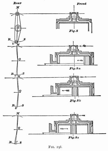 In Fig. 25b
8 we have placed the slide-valve centrally over the ports, that
is, it laps over each steam-port an equal amount, namely, w of an inch, which is equal to
the lap. In this position of the valve, the center line of the
upper rocker-arm will stand perpendicular to the line drawn parallel
to the valve-face, and the center line of the lower rocker-arm
will stand perpendicular to the center line of motion CT:
hence the center line of upper rocker-arm MQ in Fig. 25b
8 will coincide with the line MQ in Fig. 25, and the center
of lower arm QU in Fig. 25b 8 will coincide
with the line QU in Fig. 25. In Fig. 25b
8 we have placed the slide-valve centrally over the ports, that
is, it laps over each steam-port an equal amount, namely, w of an inch, which is equal to
the lap. In this position of the valve, the center line of the
upper rocker-arm will stand perpendicular to the line drawn parallel
to the valve-face, and the center line of the lower rocker-arm
will stand perpendicular to the center line of motion CT:
hence the center line of upper rocker-arm MQ in Fig. 25b
8 will coincide with the line MQ in Fig. 25, and the center
of lower arm QU in Fig. 25b 8 will coincide
with the line QU in Fig. 25.
Now let us follow the relative movement of the valve and piston.
We find, that, when the piston commences its backward motion,
the valve moves in the same direction, as shown by the arrow-points
in Fig. 25b 8a; and, during the time that the piston
is completing the half stroke, the valve has finished its full
travel backward, and commenced moving forward, as indicated by
the arrow-points, Fig. 25b 8b; and, at the time
that the piston stands exactly at half stroke, the forward edge
of the valve is just closing the forward steam-port, and consequently
cutting off steam at half stroke when the piston is moving backward.
From this we see, that, when the piston has completed the half
stroke when moving backward, the center of the valve will be a
little in the rear of the center of exhaust-port; the distance
between the center of valve and the center of exhaust-port being
w of an inch, the amount of
the lap: the upper rocker-pin will stand w
of an inch behind the line MQ and the lower rocker-arm
pin will be w of an inch in
front of the line QU, as shown in Fig. 25b 8b.
We therefore draw in Fig. 25 a straight line parallel to QU,
and w of an inch in front of
it: this line will intersect the arc RS in the point 2F3; and this
point is the position of the center of lower rocker-arm pin when
the crank stands at 2F,
and steam cut off at half stroke. Let the piston complete its
backward stroke, and then commence moving forward towards half
stroke, as shown by the arrow-point, Fig. 25b 8c. During
this time the valve has completed its full travel forward, and
commenced traveling backward, as indicated by the arrow-point,
Fig. 25b 8c; and, when the piston stands exactly at half
stroke, the rear edge of the valve is just closing the rear steam-port,
and consequently cutting off steam at half stroke when the piston
is moving forward. In this position the center line of the valve
will be w of an inch
in front of the center of exhaust, the center of the upper rocker-arm
pin will be w of
an inch in front of the line MQ, and lower rocker-pin w of an inch in the rear
of the line QU, as shown in Fig. 25b 8c.
We therefore draw in Fig. 25 a line parallel to QU, and
w of an inch behind
it; this line will intersect the arc RS in the point 2B3; and this
point will be the position of the center of lower rocker-arm pin
when the crank stands at 2B,
and steam cut off at half stroke. Now, remember, that when the
crank stands at 2F, Fig.
25, the forward eccentric will be at 2x,
and the backward eccentric at 2y;
and, if the link is raised or lowered while the eccentrics remain
at 2x 2y,
the forward eccentric-rod pin will move in the arc 2x1
2x2
and the backward eccentric-rod pin will move in the arc
2y1
2y2.
Let us now find the position of link when steam is cut off
at half stroke at either end of the cylinder.
The points 2F3
and 2B3
in Fig. 25 being located, place the paper template on the
drawing so that the point f will lie in the arc 2x1
2x2,
and the point f2 in the arc 2y1
2y2,
and the link-arc c3c4
just touching the point 2F3.
While the template is in this position, draw on the
paper along the edge c3c4
a portion of the link-arc, and mark the position that the line
ee occupied, so that, when the template is removed, the
line e1e1 can be drawn
on the paper to represent the line ee of the template.
Next place the template so that the point f will lie in
the arc ½a1 ½a2
the point f2 in the arc ½b1
½b2 and the link-arc c3c4
just touching the point ½B3 and,
while in this position, draw part of the link-arc c3c4
on the paper, mark the position that the line ee occupied,
and, after the template is removed, draw the line e2e2
on the paper to represent the line ee of the template.
Now find by trial a point x1 on the line e1e1,
and another point x2 on the line e2e2,
so that the distances of these points from their link-arcs
are equal, and that a straight line drawn through them will be
parallel to the center line of motion.
The distance from x1 to the link-arc—or,
which is the same thing, the distance from the point x2
to the link-arc—will be the correct distance between the
center of saddle-pin and the link-arc c1c2,
Fig. 6a. Or, in other words, the position of the point
x1, or x2, Fig. 25, will indicate
the proper position of the point of suspension on the link. For
future reference, let us mark this point of suspension on the
template, and indicate it by X, Fig. 6b.
PROBLEM 6, FIG. 26. — To find the position of the center
of lifting-shaft and the length of its arms.—In the last
problem we found the point of suspension of the link, so that
it will cause the valve to cut off equal portions of steam when
the piston stands at half stroke. It now remains for us to find
the position of the lifting-shaft and the length of the lifting-shaft
arms, so that the greatest equal amounts of steam will be admitted
alternately at each end of the cylinder. Here a little difficulty
arises which needs explanation, so that our construction may not
seem inconsistent to the reader. It would be an easy matter to
place our lifting-shaft to accomplish the object just stated;
but, if we do this, the lead will not be equal at each end of
cylinder when the piston is at full stroke. Again, if we locate
our lifting-shaft in such a manner that equal lead will be obtained,
then the maximum cut-off will not be equal; but the difference
will be comparatively so small that it will not injure the working
of the engine. This small difference of the maximum cut-off is
therefore considered among practical men of little or no importance,
but it is always considered good practice to have an equal lead
at full stroke. Let us therefore adjust the lifting-shaft to obtain
an equal lead, and allow us to consider the maximum cut-off to
be equal when the lead is equal at full stroke.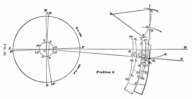 For this problem we have to combine
all the foregoing problems. Through the center C of axle
draw the horizontal line AD, and the line KL perpendicular
to it. Find the positions of crank at full and half stroke, as
per Problem 1. Locate the rocker, draw the center line of motion
CT, and amount of offset in lower rocker-arm, according
to Problem 2. Next, locate the relative positions of eccentrics
when the crank stands at full and half stroke, as explained in
Problem 3. Then with a radius equal to the correct length of eccentric-rods,
as explained in Problem 4, draw For this problem we have to combine
all the foregoing problems. Through the center C of axle
draw the horizontal line AD, and the line KL perpendicular
to it. Find the positions of crank at full and half stroke, as
per Problem 1. Locate the rocker, draw the center line of motion
CT, and amount of offset in lower rocker-arm, according
to Problem 2. Next, locate the relative positions of eccentrics
when the crank stands at full and half stroke, as explained in
Problem 3. Then with a radius equal to the correct length of eccentric-rods,
as explained in Problem 4, draw
From the point x as a center, the arc x1
x2
From the point y as a center, the arc y1
y2
From the point ½x as a center, the arc ½x1
½x2
From the point ½y as a center, the arc ½y1
½y2
From the point a as a center, the arc a1
a2
From the point b as a center, the arc b1
b2
From the point ½a as a center, the arc ½a1
½a2
From the point ½b as a center, the arc ½b1
½b2
Locate the points ½B3 and ½F3,
indicating the position of the center of lower rocker-pin when
steam is cut off at half stroke; find the points x1
x2, indicating the positions of the point of
suspension when the link is lifted into the position to cut off
at half stroke, as explained in Problem 5, and shown in Fig. 25.
Now, in order to find the position of lifting-shaft and length
of arms, we must find four more additional points, —first,
the position of the point of suspension of the link when the piston
is at full stroke forward end of cylinder, and the crank-pin at
F, the valve having z of
an inch lead, and the engine moving forward, as indicated by the
arrow-point I; also the position of the point of suspension of
the link when the piston is at full stroke at the opposite end
of the cylinder, valve z inch
lead, and engine going in the same direction. To find these two
points, we must know the corresponding position of the center
of lower rocker-pin. In Fig. 25b 8a we see, that when the
piston is at full stroke forward, and valve with inch lead, the
center of valve is M of an
inch in the rear of the center line of exhaust, and consequently
the lower rocker-pin will be M
of an inch in front of the line QU. In the same manner
we can show that the center of lower rocker-pin will be M of an inch in the rear of the
line QU when the piston is at the opposite end of the cylinder.
Let us now locate the positions of the lower rocker-pin in
Fig. 26, by drawing a line parallel to and in front of QU,
with M of an inch between them:
this line will intersect the arc RS in the point F3,
and this point will be the center of lower rocker-pin when the
piston is at full stroke forward. Draw another line M
of an inch in the rear of QU and parallel to it:
this line will intersect arc RS in the point B3,
and this point will be the center of rocker-pin when the piston
is at full stroke in the rear end of the cylinder. Now place the
paper template with the line ee below the center line of
motion CT, the point f1, on the arc x1
x2, the point f on the arc y1
y2, and the link-arc c3c4
just touching the point F3, and, while in this
position, mark the point X of the template on the paper,
which can be done with the aid of a needle, and indicate the point
on the paper by x3. This point will be the position
of the center of saddle-pin when the piston is at full stroke
in the forward end of the cylinder, the valve having z
inch lead. Again, slide the template along until the point
f is on the arc a1 a2,
the point f2 on the arc b1
b2, and the link-arc c3
c4 in contact with the point B3;
mark the point X of the template on the paper, and indicate
this point by x4. This point will be the position
of the center of saddle-pin when the piston is at full stroke
in the rear end of the cylinder, the valve having z
inch lead. Secondly, to find the position of the point of suspension
of the link when the piston is at full stroke in the forward end
of the cylinder, valve having z of
an inch lead, and the engine moving backward, as indicated by
the arrow-point 2; also the position of the point of suspension
of the link when the piston is at full stroke at the opposite
end of the cylinder, valve z of
an inch lead, engine going in the same direction. For this purpose,
slide the template along until the line cc is above the
line CT, and f in the arc a1 a2,
the point f2 in the arc b1
b2 and the link-arc c3
c4 in contact with the point B3;
mark the point X on the paper, and indicate this point
by x5. This point will be the position of the
center of saddle-pin when the piston is at full stroke in the
rear end of the cylinder, valve having z
of an inch lead. Again, slide the template along until
the point f will be in the arc x1 x2,
point f2 in the arc y1 y2,
and the link-arc c3 c4 in
contact with the point F3; mark the point X
on the paper, and indicate this point by x6.
This point will be the position of the center of saddle-pin (or
the point of suspension) when the piston is at full stroke in
the forward end of the cylinder, valve z
of an inch lead, engine moving backward. Now, once more, with
the point x3 as a center, and with the length
of the link-hanger as a radius, describe an arc ; and with the
point x4 as a center, and the same radius, describe
another arc. These two arcs will intersect each other in the point
g. Again, with the length of the link-hanger as a radius,
and the points x1 x2 as centers,
describe two arcs intersecting each other in the point g1,
with the points x5 x6 as centers; and, with
the same radius, describe another two arcs intersecting each other
in the point g1. Lastly, through the points
g g1 g2, draw an arc.
The center h, from which the arc has been described, will
be the center of the lifting-shaft, and the radius hg or
hg2 will be the length of the lifting-shaft
arms ; that is, the length of the two arms to which the link-hangers
arc attached : the length of the other lifting-shaft arm, to which
the reach-rod is attached, is made to suit the other details of
the engine.
When the admittance of steam ceases at the same time that the
piston has reached the half stroke, the practical man would say
"that the valve is cutting off equal at half stroke."
When the greatest equal volume of steam is admitted alternately
in each end of the cylinder, the valve is said to be cutting off
equal when the link is in full gear.
It is always conceded among engineers, that when the link-motion
is adjusted to cut off equal at half stroke, and also to cut off
equal when the link is in full gear, equal volumes of steam will
be admitted alternately when the link hangs at any intermediate
point.
If, now, we examine Problem 5, we find, that, to obtain an
equal cut-off at half stroke, it is necessary to find the proper
position of saddle-pin.
Again, if we examine Problem 6, we find, that, in order to
obtain an equal cut-off when the link is in full gear, also an
equal cut-off for any point between full gear and half stroke,
we have to determine the proper position of the center of lifting-shaft
and the correct length of its arms.
Lastly, if we examine the first four problems, we find them
simply to be preparatory problems.
According to promise, we will draw attention to those points
which have been, and others which have not been, approximately
found. Problems 1, 2, and 3 are theoretically correct. In Problems
4, 5, and 6, the use of the template will not be admitted for
theoretical reasoning; but, if the construction is made with absolute
accuracy, the result will be theoretically correct.
The following are a few dimensions of locomotives made by well-known
makers:—
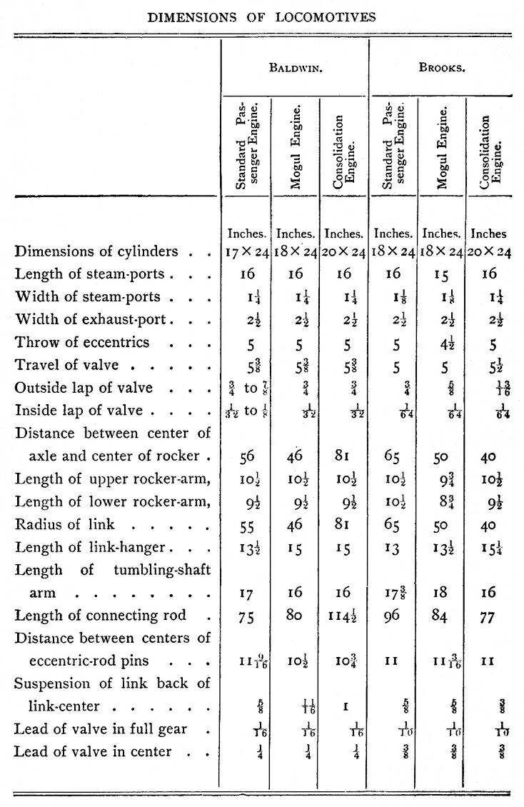
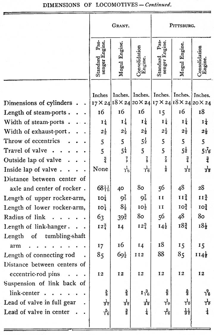
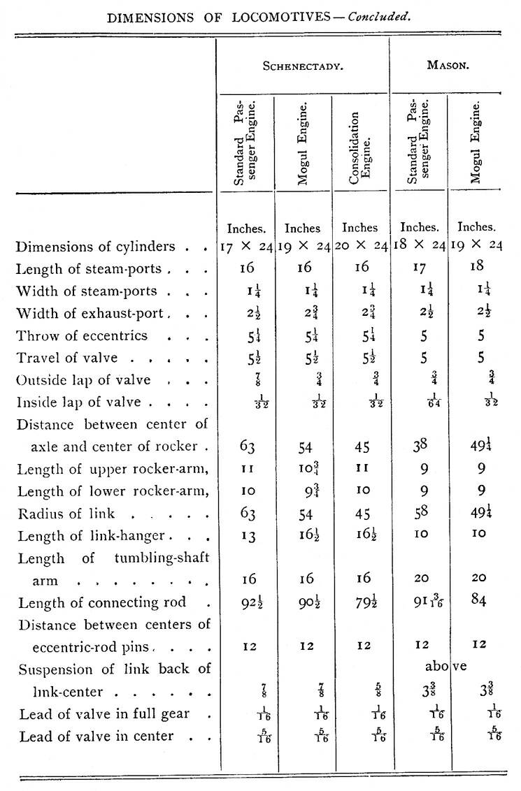
Table of Contents
| Contents Page
|


