|
CHAPTER XXI.
THE WESTINGHOUSE AIR-BRAKE.
INVENTION OF THE WESTINGHOUSE ATMOSPHERIC
BRAKE.
IN this exacting age, the traveling public are much
more disposed to find fault with systems that do not provide against
fatalities resulting from human fallibility, than to commend the
perfection of appliances which annually save more lives than would
be lost in a sanguinary war. The Westinghouse brake has performed
this life-saving service, yet its great conserving merit has been
but feebly appreciated outside of railroad circles. During the
decade between 1860 and 1870, America became a reproach among
nations for the frequency and disastrous nature of its railroad
accidents. To-day fewer railroad travelers in America lose their
lives by accidents beyond their own control, than the travelers
in any country under the sun. The credit of this immunity from
fatal accidents is almost entirely due to the successful operation
of the Westinghouse and other brakes that followed the line suggested
by this invention.
DISTINCT CLASSES OF INVENTIONS.
Inventions may be divided into two distinct classes.
Far the more numerous class are those which effect improvements
on recognized appliances. The other is the rare and more valuable
class, to which belongs the original inventor who devises an entirely
new method for performing a desired operation. Among this class
of inventions may be noted Watt's separate condenser, which first
rendered the steam engine a commercial success; the multi-tubular
boiler of Nathan Read, which made a high-speed locomotive practicable;
and the airbrake of Westinghouse, which made fast traveling safe,
by putting the train speed under the control of the engineer.
BENEFITS CONFERRED ON TRAIN MEN BY GOOD
BRAKES.
To the traveling public the air-brake has proved a
source of satisfaction by assuring exemption from accidents, but
its greatest blessing has been conferred upon train men. Being
the greatest sufferers from railway accidents, their risks of
life and limb are greatly reduced; and the agonizing helplessness
that used to be so often experienced with trains that could not
be stopped in time to avoid a disaster, is almost unknown on our
well-managed roads. Mind has become victor in its conflict with
matter. When necessary, an engineer can run a train at a high
velocity over crowded lines without having to shut off steam within
a mile of each point where there may be another train obstructing
the track, or keep up his speed at the risk of his life. People
unacquainted with the inside operating of railroads have no idea
of the difficulties train men had to contend with in getting fast
trains over the road, before continuous brakes were supplied.
The train had to be run on schedule time, and all points where
trains might be expected had to be approached with care. This
meant reduced speed; and speed could not be reduced in short distances,
so the risk had to be taken of violating one rule to comply with
another.
ESSENTIAL PARTS OF THE WESTINGHOUSE AUTOMATIC
AIR-BRAKE.
The prominent features of the Westinghouse automatic air-brake
consist of the following leading parts:
An air-pump, placed on the locomotive, is operated by a steam
cylinder, which forces air into an iron drum or reservoir placed
under the deck, or in any other convenient part about the engine.
The air is compressed to the density considered necessary for
the kind of train the locomotive usually pulls.
In the cab, located conveniently to the hand of the engineer,
is the engineer's brake-valve, commonly called the "three-way
cock," which regulates the flow of air from the main reservoir
into the main brake-pipes for supplying the auxiliary reservoirs
with air. This valve applies the train-brakes by letting the air
escape from the main brake-pipes, and releases them by again admitting
the pressure of air into the pipes.
From the main reservoir, the main brake-pipe connects with
the engineer's valve, and thence along the train, supplying all
the brakes with the air required.
Under the floor of each car is fastened an auxiliary reservoir,
which holds a supply of air necessary for operating the brakes
on that car. So each car carries its own supply of air.
Connected with each car-truck is a brake-cylinder, in which
is operated a piston that applies the brake. The brake-levers
connect with the piston-rod in such a manner, that, when the piston
is forced out by the air-pressure, the brake is applied.
Attached to the auxiliary reservoir is the triple valve, whose
action connects the air-cylinder with the auxiliary reservoir.
THE AIR-PUMP.
When the air-brake was first invented, the distribution
of steam within the cylinder was effected differently from what
it is in modern pump-cylinders. The steam-valve consisted of a
double piston, the beads having ports on their edges which admitted
and released. the steam. This valve did not move up and down,
but received an oscillatory motion from a small auxiliary engine
placed on the top of the steam cylinder-head. The movements of
the auxiliary engine were regulated by a reversing-rod (popularly
known as a kicker-rod), working inside the main piston-rod. This
arrangement of steam distribution was somewhat complicated, and
liable to get out of order; and it was superseded by the differential
steam-valve movement now in use.
HOW THE AIR-PUMP WORKS.
In Fig. 27a, steam enters from the boiler at the nipple
35, and fills the steam-space between the heads of the main piston-valve
15, 16, maintaining a constant pressure of steam there while the
pump is at work. The upper head of the main valve being of greater
area than the lower one, the tendency of the pressure is to raise
the valve. A downward movement of the valve is provided for by
a separate single-headed piston-valve 20, working in a cylinder
above the main valve. The reversing-rod 12 operates a slide-valve
13, which regulates the admission and release of steam for the
third piston.
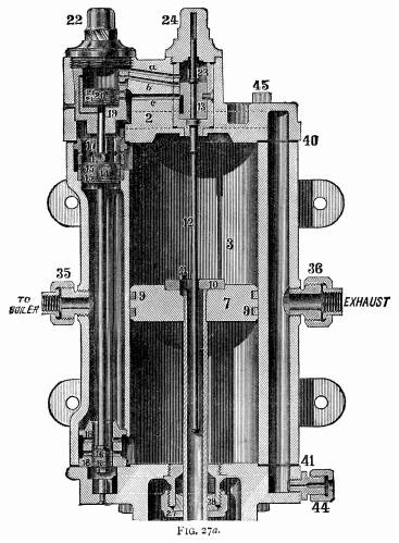 In the cylinder
shown in the engraving, the main valve is down, so that steam
is passing into the lower end of the main cylinder. Two small
ports can be seen close to the piston-head 16, one above the other.
The upper port is open, and is the admission port: the lower port,
which is closed by the small piston, is for exhausting the steam.
The main piston 7 is on its upward stroke, and the upper exhaust
port seen above the piston-valve 15 is open, while the steam port
immediately below it is closed by the valve-piston in the same
way that the exhaust port is closed at the other end. When the
main piston 7 shall reach near the top of its upward stroke, the
plate 10 will strike on the projection on the reversing-rod, pushing
up the slide-valve Q. The upper edge of this slide-valve
will cut the steam off the passage a, and open the passage
b to the exhaust. This takes the steam away from the piston
20, and allows piston 15 to move upward, closing the exhaust-port,
and opening the upper steam-port. The same movement makes the
piston 16 close its steam-port, and open the exhaust. Piston 7
now begins to travel downward; and, when it reaches nearly to
the bottom of the cylinder, the plate 10 catches the knob on the
end of the reversing-rod, and pulls down the slide-valve 13 to
the position it holds in the engraving. Steam then rushes through
the passage a, and makes the piston 20 push down the main
valve. That completes the circle of the operations in the steam
cylinder. In the cylinder
shown in the engraving, the main valve is down, so that steam
is passing into the lower end of the main cylinder. Two small
ports can be seen close to the piston-head 16, one above the other.
The upper port is open, and is the admission port: the lower port,
which is closed by the small piston, is for exhausting the steam.
The main piston 7 is on its upward stroke, and the upper exhaust
port seen above the piston-valve 15 is open, while the steam port
immediately below it is closed by the valve-piston in the same
way that the exhaust port is closed at the other end. When the
main piston 7 shall reach near the top of its upward stroke, the
plate 10 will strike on the projection on the reversing-rod, pushing
up the slide-valve Q. The upper edge of this slide-valve
will cut the steam off the passage a, and open the passage
b to the exhaust. This takes the steam away from the piston
20, and allows piston 15 to move upward, closing the exhaust-port,
and opening the upper steam-port. The same movement makes the
piston 16 close its steam-port, and open the exhaust. Piston 7
now begins to travel downward; and, when it reaches nearly to
the bottom of the cylinder, the plate 10 catches the knob on the
end of the reversing-rod, and pulls down the slide-valve 13 to
the position it holds in the engraving. Steam then rushes through
the passage a, and makes the piston 20 push down the main
valve. That completes the circle of the operations in the steam
cylinder.
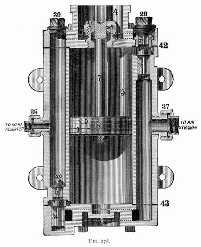 HOW THE AIR-END OPERATES. HOW THE AIR-END OPERATES.
The operation of the air part of the pump is very simple.
While the main piston (Fig. 27b), which is on the same rod as
the piston of the steam cylinder, is moving upward, it is forcing
the air out of the upper end of the cylinder up under the discharge-valve
32, and away through the proper passages to the main reservoir.
At the same time the lower end of the cylinder is being filled
with air drawn through the lower receiving-valve 34. During the
downward stroke of the piston, the air will be delivered through
the valve 33, and the upper part of the cylinder filled by air
received through the upper valve 34.
AIR-PUMP DISORDERS.
An engineer who does not understand the principles
of a locomotive's action, is not likely to prove a valuable runner.
The men who are most successful in getting trains over the road
with solar regularity; the men who make the best records on the
mileage sheets for economy in fuel and in lubricants; who are
lightest in repairs, yet keep their engine going longest, —
are those who comprehend the functions of every portion of the
engine, and what relation the various parts bear to each other.
With this knowledge clearly established in the mind of the runner,
his power to detect any thing wrong with his engine becomes instinctive.
Trifling defects, which neglect would develop into serious disabilities,
are rectified in time, and the whole engine is maintained in smooth
working-order by the harmony of its individual sections. The mere
stopper and starter is losing his hold on the locomotive service.
When he drops off entirely, our mileage for each dollar expended
will be decidedly increased.
The principles which apply to the running of a locomotive are
equally applicable to the management of an air-brake, with all
its perfected connections. This apparatus can not be properly
managed unless the man who works it knows something about its
action.
PUNY DIFFICULTIES VANQUISH THE IGNORANT
ENGINEER.
A great many engineers who run passenger trains, and
take an intelligent interest in the working of the locomotive,
whose technicalities they have thoroughly mastered, display no
desire whatever to understand the air-brake, and are perfectly
contented with its action so long as it will stop the train. The
air-pump, so wonderfully interesting to those who understand its
movements, receives no more attention than is necessary to keep
it going so that the required air-pressure is maintained. They
know how to start and stop the machine, and they oil it regularly;
but these are the limits of their attentions. Should the pump
happen to stop working, the cause is mysterious, like many other
mysteries; and the natural remedy suggested, is to hit the thing
on the head with a monkey-wrench. Should it not respond to this
treatment by renewed action, the hand-brakes are resorted to for
the rest of the journey; and the roundhouse foreman or machinist
is required to do the head, work which locates the trouble.
A belief prevails among men who labor principally with their
hands, that laziness is exclusively physical. This is a mistake.
It is a psychological fact, well known to metaphysicians, that
mental laziness is prevalent enough to dwarf the minds of half
the human race. Men who would willingly work with their hands
during half their leisure time to keep their engines in proper
condition for running, have to be driven, by fear or jealousy,
before they will force their mental faculties to do trifling labor
in a new channel.
CAUSES THAT MAKE BRAKES INOPERATIVE OFTEN
EASILY REMEDIED.
Any engineer of ordinary intelligence, who will spend
one hour a day for two weeks studying up the Westinghouse instruction
book, will understand the brake so well, from the pump to the
hind end of the train, that any imperfection happening to its
working will be as readily located as an ordinary defect in a
locomotive. Yet it is an intensely hard matter to induce men running
passenger engines to go through this trifling mental exercise.
The consequence is, that the brake sometimes becomes inoperative
from causes so slight that men should be ashamed to report them;
and they, would be so if they only comprehended how small a mole-heap
became their mountain. I knew a case where all the train men —
that is to say, engineer, fireman, conductor, baggageman, and
brakemen wrestled for twenty minutes over a triple valve, trying
to find out how to cut the air off a car; and, when the crowd
was vanquished, a colored porter came, and showed them how the
thing was done. This was on a road where straight air was generally
used. One day some winters ago, a passenger train on the road
I worked for was delayed an hour or more at a station, waiting
for something, When the engineer tried to start the air-pump,
it would not work. He fumed and fussed over it for fifteen minutes,
gave it a liberal dose of copper hammer medicine, and saturated
it with oil, but all to no purpose. It would not pump a pound
of air, so the old-fashioned Armstrong was called into operation.
In the course of its journey, this train had to pass the round-house
at headquarters ; and the engineer stopped to see if his pump
could be given some quick remedy. I happened to be the doctor
consulted. On learning the particulars of how the pump stopped
working, I set fire to a piece of greasy waste, and held the flame
to the check-valve of the air-drum; and the pump went right to
work. All the trouble was, that the check-valve was frozen in
its seat. I felt sorry for that engineer, he appeared to be so
thoroughly ashamed and crestfallen at being baffled by such a
small trouble.
CARE OF THE AIR-PUMP.
To run an air-pump successfully, the first requisite
is that it should be managed intelligently, and its wants attended
to regularly. An air-pump consists of numerous moving parts, which
should operate with the least possible amount of friction: consequently,
it is important that the machine should be properly lubricated,
not deluged with grease for ten minutes, and then run on the interest
of the excess for two hours, but sparingly furnished with clean
oil which will keep the moving parts moist all the time. To accomplish
this, the feeding-cup must be kept in proper working-order, so
that it will pass the oil regularly. I have found a leading cause
for air-pumps working unsatisfactorily to be in the intermittent
feeding of the oil-cups. Some dirt gets into the cup, obstructing
its action, and greater opening is given to make it feed; then
the oil goes through by spasms, and the pump works irregularly;
for at one time the steam-piston is churning the oil, and again
it is working dry. There is also a common abuse of the oilcan
when any thing goes wrong with the pump; for some men will then
drench it with oil, expecting that to make it work smoothly. Permanent
injury is often done in this way, especially where inferior oils
are used, which frequently contain mineral substances in suspension.
This solid matter is separated from the oil by the heat, and settles
in the small passages, filling them up by degrees till eventually
there is no channel left for the steam to pass through to reverse
the steam-valve; so the pump stops. I once saw a runner trying
to doctor a sick pump by pouring the stickiest kind of gummy valve-oil
into an air-cylinder. He gave the thing its quietus, as other
poor doctors sometimes do with their patients.
PUMP PACKING.
The stuffing-box packing is not generally supposed
to exercise an important effect on the action of an air-pump;
yet I have seen cases where irregular action of the pump, and
serious loss of air, resulted from bad packing. Soapstone and
asbestos, and other substances that become compact and rigid when
cold, are unsuitable for packing the air end of a pump. After
a little use, material of this kind becomes so hard that no amount
of screwing of the gland will make it tight; and the greater part
of the air at that end of the pump escapes through the stuffing-box
instead of passing into the drum.
HOW STEAM PASSAGES GET CHOKED.
Around the bushings of the cylinder, where the small
reversing piston 20 works, are diminutive steam passages, very
liable to get stopped up when foreign matter is attempted to be
run through the cylinder. Such matter is occasionally introduced
in various ways. When rubber gaskets are used in the pipe connections
leading to the cylinder, the rubber often peels off in shreds,
or breaks off in small pieces, which lodge around the bushing
in the passages, producing harassing annoyance. So soon as those
passages get obstructed, or reduced below their correct size,
the pump begins to work badly. Machinists not well versed in the
mysterious ways of air-pump disorders will now take that pump
apart, and find nothing the matter. Subsequent proceedings depend
upon the nature of the man who has the job in hand. If the machinist
be of a conservative disposition, he will put the apparatus together
again without making any alteration, and perhaps will relieve
his mind by expressing a belief that the engineer does not know
when an air-pump is in good shape. Another machinist, of a more
enterprising stamp, must find something to change, so he lengthens
or shortens the reversing valve-rod 12 (a favorite resort of small-knowledge
tinkers), which gives the pump the coup de grâce; and
it has to be over. hauled by a competent machinist before it again
supplies the air to stop a train. This competent man goes direct
to the root of the trouble. Skill in this particular line of work
convinces him, after an examination, that the moving parts require
no repairs; and knowledge begotten of experience, supplemented
by sound sense, directs him where to look for the cause of defective
operation.
SAGACITY NEEDED IN REPAIRING AIR-PUMPS.
Men who meet with good success in repairing air, pumps,
and in determining, from the action of the pump the probable cause
of defect, have to do a great deal of deep and sagacious thinking.
Sometimes a defect, simple enough in itself, is extremely difficult
to locate, because it belongs to the unexpected order of occurrences.
Here was an instance. Some small jobs had been done one day
to the steam cylinder of a pump which had not been working quite
satisfactorily. When they tried to start it, after being put together,
the pump would not work at all. The machinist who did the job,
an eminently competent man at such work, took the machine apart
again, but could detect no defect or maladjustment about it. The
steam cylinder, with all its valves and rods and bushings, was
critically examined: the air-pump, with all its connections, got
a thorough inspection to no purpose. When an ordinary man goes
through the patient, thoughtful labor needed for an examination
of this kind, and finds nothing wrong, he is apt to get discouraged,
and confess himself beaten. This man did not recognize the word
beaten as applied to his work. He reasoned, "This pump would
work if it were all right. It will not work, so something must
be wrong." After exercising more patience and perseverance,
he discovered that the bushing 23 of the reversing valve (usually
called the kicking-rod valve) had become loose, and, when the
cap was screwed down, it twisted the bushing round, and closed
the passages that lead steam to the reversing piston. There are
small grooves round the sides of the small steam passages to provide
for the bushings being moved a little, but these grooves had become
gummed up so that they failed to serve their purpose of keeping
the ports open.
GRADUAL DEGENERATION OF THE AIR-PUMP.
The working and stationary parts within the cylinders
of the air-pump are adjusted with nice exactness; and, when they
remain in their normal condition, the pump works smoothly, and
compresses air rapidly. When wear, or any other cause, alters
the dimensions of these parts, the effect immediately becomes
apparent in unsatisfactory working of the whole machine. Rods
are adjusted so that valves or pistons shall cover and uncover
steam passages, and no superfluous movement is provided for. The
passages are so small that all the steam they convey is needed
for the work of reversing the motion; and if from any cause the
valve or piston only partly uncovers the opening, the necessary
volume of steam does not get through. A close observer of the
pump's action can, day by day, perceive the gradual degeneration
due to wear. Wear of the steam-cylinder connections is generally
indicated by reduced power. The pump will not do its work satisfactorily,
and has difficulty in keeping up the pressure of air. This deterioration
continues till the pump will stop, unless its decay gets arrested
by repairs. When the valves of the air-pump are in correct order
for doing good work, the discharge-valves 32 and 33 have Z of an inch, and the suction-valves
34 8", lift. The continual
tapping of these valves on their seats has a tendency to wear
out valves and seats, making the lift greater than what is desirable.
Any material increase of lift for the discharge-valve has a most
injurious effect upon the motion of the pump, especially if the
suction-valve should happen to be leaky. Then the movement of
the pistons will become fluctuating, and subject to frequent stoppages.
The up-and-down motion of the piston is of a jerky character,
that makes the beholder suppose the thing is uncertain which way
to go. Deterioration of air-valves is not, however, the only cause
for that jerky motion so often observed in bad working pumps.
A bent reversing valve stem (kicker-rod) acts on the reversing
valve with oblique pull and thrust, which tend to move it away
from the seat, letting the steam pass the wrong way. A broken
main steam-valve ring has a similar effect; for the steam passes
to the wrong end of the valve, destroying its equilibrium; and
there is nothing decisive about its reversal, or about its motion
after it is reversed. Its action resembles the movements of a
vacillating human being. It does not want to go in that direction,
but goes, then keeps trying to change its mind during the rest
of the journey. Obstructed steam passages will sometimes cause
indecisive action of the pump before it gets bad enough to stop
it altogether.
When one of the exhaust ports begins to get filled up sufficiently
to interfere with the action of the pump, the effect will be that
the main piston will very slowly approach the end where the trouble
is, and then make the opposite stroke with a quick motion. The
contracted passage leaves some steam in the cylinder which is
compressed, causing slow movement, and the compressed steam helps
to give velocity to next stroke.
CAUSES THAT MAKE A PUMP POUND.
Pounding on the heads is a somewhat common attribute
of degenerated air-pumps. Broken or badly worn air-valves very
often cause the pump to pound. If the trouble should happen to
be in the upper air-valve, it will demonstrate its disorder by
causing pounding on the upper head; and the lower valve's malady
will cause pounding on the lower head. When a pump is suffering
from indecisive motion, or is pounding, and the machinist does
not feel certain about where the trouble lies, he may safely examine
the condition of the air-valves, —for they can be easily
reached,— and in a great many cases the defect will be found
there. Wear of the pin whereon the bottom of the main valve-rod
rests, or of the rod itself, will induce pounding on the tipper
head by the main piston.
I have known of a disastrous effect being produced on a pump
by putting a new gasket, which proved too thick, on the upper
head. It was the thinnest copper that could be found, but it perceptibly
lengthened the upper end of the cylinder so that the bottom knob
on the reversing stem struck the reversing plate on the main piston
before that action was due. On several occasions I have had air-pumps
reported to be working badly, when all the trouble lay in the
air-strainer being partly choked up by floating vegetable matter
that had been sucked in with the air, and failed to pass through
the meshes. In another case we had much difficulty in locating
the defect, with a pump that absolutely refused to work. The boiler-makers
had been working in the smoke-box, and by some means the end of
the exhaust-pipe got solidly stopped up with cinders. As none
of us had come across that particular cause of obstruction before,
we expended a good deal of labor searching for the trouble before
we thought to disconnect the exhaust-pipe from the pump.
 THE TRIPLE VALVE. THE TRIPLE VALVE.
This is the part whose operation gives the brake its automatic
action. Those who have opposed this form of brake have made great
objection to the complicated nature of the triple valve. But some
familiarity with the device shows that it is far from being complex,
considering the functions it performs. It is merely a piston-valve
carrying a slide-valve along with it.
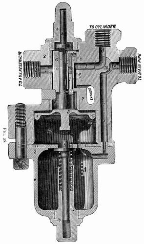
The arrangement of the parts of the triple valve is shown in
Fig. 28.
The triple valve has a piston 5, working in the chamber B,
and carrying with it the slide-valve 6. Air enters from the main
pipe through the four-way cock 13 into the drain-cup A,
and passes to the chamber B, forcing the piston up, and
uncovering a small feeding-groove in the upper part of the chamber,
which permits air to flow past the piston into the auxiliary reservoir,
while, at the same time, there is an open communication from the
brake-cylinder to the atmosphere through the passages d, e,
f, and g. Air will continue to flow into the auxiliary
reservoir until it contains the same pressure as the main brake-pipe.
ACTION OF THE TRIPLE VALVE.
To apply the brakes with their full force, the compressed
air in the main brake-pipe is permitted to escape, when the greater
pressure in the auxiliary reservoir forces the piston 5 down below
the feeding-groove, thus preventing the return of air from the
reservoir to the brake-pipe. As the piston descends, it moves
with it the slide-valve 6, so as to permit air to flow directly
from the auxiliary reservoir into the brake-cylinder, which forces
the pistons out, and applies the brakes. The brakes are released
by again admitting pressure into the main brake-pipe from the
main reservoir; which pressure, being greater than that of the
auxiliary reservoir, forces the piston 5 back to the position
shown in the engraving, recharges the reservoir, and at the same
time permits the air in the brake-cylinders to escape.
To apply the brakes gently, a slight reduction is made in the
pressure in the main brake-pipe, which moves the piston down slowly
until it is stopped by the graduating spring 9. At this point,
the opening l in the slide-valve is opposite the port f,
and allows air from the auxiliary reservoir to feed through a
hole in the side of the slide-valve, and through the opening l
into the brake-cylinder. The passage l is opened and closed
by a small valve 7, which is attached to, and moves with, the
piston 5, provision being made for a limited motion of these parts
without moving the valve 6. When the pressure in the auxiliary
reservoir has been reduced by expanding into the brake-cylinder
until it is the same as the pressure in the main brake-pipe, the
graduating spring pushes the piston up until the small valve 7
closes the feed opening l. This causes whatever pressure
is in the brake-cylinder to be retained, thus applying the brake
with a force proportionate to the reduction of pressure in the
brake-pipe.
TO PREVENT CREEPING ON OF BRAKES.
To prevent the application of the brakes, from a slight
reduction of pressure caused by leakage in the brake-pipe, a semicircular
groove is cut in the body of the car-cylinder, nine-sixtyfourths
of an inch in width, five-sixtyfourths of an inch in depth, and
extending so that the piston must travel three inches before the
groove is covered by the packing leather. A small quantity of
air, such as results from a leak, passing from the triple valve
into the car-cylinder, has the effect of moving the piston slightly
forward, but not sufficiently to close the groove, which permits
the air to flow out past the piston. If, however, the brakes are
applied in the usual manner, the piston will be moved forward,
notwithstanding the slight leak, and will cover the groove. It
is very important that the groove shall be three inches long,
and shall not exceed in area the dimensions given above. Heretofore
leakage valves have been used, and also a leakage hole. These
leakage holes have been found to be too uncertain in their operation;
and consequently it is recommended that these holes should be
closed, and the grooves in the cylinders substituted, as rapidly
as possible.
When the handle of the four-way cock 13 is turned down, there
is a direct communication from main brake-pipe to the brake-cylinder,
the triple valve and auxiliary reservoir being cut out; and the
apparatus can be worked as a non-automatic brake, by admitting
air into the main brake-pipe and brake-cylinder, to apply the
brakes. When from any cause it is desirable to have the brake
inoperative on any particular car, the four-way cock is turned
to an intermediate position, which shuts off the brake-cylinder
and reservoir, leaving the main brake-pipe unobstructed to supply
air to the remaining vehicles.
The drain-cup A collects any moisture that may accumulate,
and is drained by unscrewing the bottom nut.
HOW TO APPLY AND RELEASE THE BRAKE.
The brakes, as has been explained, are applied when
the pressure in the brake-pipe is suddenly reduced, and released
when the pressure is restored.
It is of very great importance that every engineer should bear
in mind that the air-pressure may sometimes reduce slowly, owing
to the steam-pressure getting low, or from the stopping of the
pump, or from a leakage in some of the pipes when one or more
cars are detached for switching purposes, and that in consequence
it has been found absolutely necessary to provide each cylinder
with the leakage groove already referred to, which permits a slight
pressure to escape without moving the piston, thus preventing
the application of the brakes, when the pressure is slowly reduced,
as would result from any of the above causes.
This provision against the accidental application of the brakes
must be taken into consideration, or else it will sometimes happen
that all of the brakes will not be applied when such is the intention,
simply because the air has been discharged so slowly from the
brake-pipe that it only represents a considerable leakage, and
thus allows the air under some cars to be wasted.
It is thus very essential to discharge enough air in the first
instance, and with sufficient rapidity, to cause all of the leakage
grooves to be closed, which will remain closed until the brakes
have been released. In no case should the reduction in the brake-pipe
for closing the leakage grooves be less than four or five pounds,
which will move all pistons out so that the brake-shoes will be
only slightly bearing against the wheels. After this first reduction,
the pressure can be reduced to suit the circumstances.
On a long train, if the three-way cock be opened suddenly,
and then quickly closed, the pressure in the brake-pipe, as indicated
by the gauge, will be suddenly and considerably reduced on the
engine, and will then be increased by the air-pressure coming
from the rear of the train: hence it is important to always close
the three-way cock slowly, and in such a manner that the pressure,
as indicated by the gauge, will not be increased; or else the
brakes on the engine and tender, and sometimes on the first one
or two cars, will come off when they should remain on. It is likewise
very important, while the brakes are on, to keep the three-way
cock in such a position that the brake-pipe pressure can not be
increased by leakage from the main reservoir; for any increase
of pressure in the brake-pipe causes the brakes to come off.
On long down grades, it is important to be able to control
the speed of the train, and at the same time to maintain a good
working pressure. This is easily accomplished by running the pump
at a good speed, so that the main reservoir will accumulate a
high pressure while the brakes are on. When, after using the brake
some time, the pressure has been reduced to sixty pounds, the
train pipes and reservoirs should be recharged as much as possible
before the speed has increased to the maximum allowed. A greater
time for recharging is obtained by considerably reducing the speed
of the train just before recharging, and by taking advantage of
the variation in the grades.
There should not be any safety-valve or leaks in the main reservoir,
otherwise the necessary surplus pressure for quickly recharging
can not be obtained.
To release the brakes with certainty, it is important to have
a higher pressure in the main reservoir than in the main pipe.
If an engineer feels that some of his brakes are not off, it is
best to turn the handle of the three-way cock just far enough
to shut off the main reservoir, and then pump up fifteen or twenty
pounds extra, which will insure the release of all of the brakes;
all of which can be done while the train is in motion.
For ordinary stops, great economy in the use of air is effected
by, in the first instance, letting out from eight to twelve pounds
pressure while the train is at speed, taking care to begin a sufficient
distance from the station.
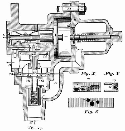 THE QUICK-ACTION VALVE. THE QUICK-ACTION VALVE.
When the application of air-brakes to freight trains
began to be a recognized necessity, it was found that the common
automatic brake was too slow in its action for handling a train
of fifty cars smoothly. The required quickness of action was provided
by Mr. Westinghouse in the invention of the Quick-action Triple
Valve, illustrated in Fig. 29.
This triple valve stands horizontally instead of vertically
as the old one is set, and it retains all its former features,
while those that are added are improvements. The casing of the
triple valve has three branches, C, B, and E
(seen in Fig. 29), connected respectively to the auxiliary
reservoir, the brake-cylinder, and the train-pipe. Branch E
has access by the passage K and openings ll
with a cylinder in which is the piston-valve 5. The opposite side
of this piston is in direct connection with the reservoir through
the opening C, and, when the parts are in the position
shown, compressed air from the train-pipe can flow past the piston
5, through the grooves d and f, until the pressure
in the reservoir is equal to that in the train-pipe. During the
time the interior of the brake-cylinder is connected to the atmosphere
through the branch B, the passage a, the port a
(Fig. Z, and also shown in dotted lines in Fig. 29), the
cavity b (Figs. 29 and X) of the slide-valve 6,
and the port c which emerges into the open air. If now
the pressure in the train-pipe be slightly reduced by opening
the engineer's valve, the piston 5 will be moved to the right
by the expansion of the air in the reservoir, but under ordinary
circumstances it will only move through half of its available
travel, in consequence of the pressure in the reservoir being
reduced to that in the train-pipe by a part of the air rushing
into the brake-cylinder in the following way: The rod of the piston
5 passes through the slide-valve 6, the connection between the
two being so made that the piston can move a small distance without
moving the valve. When the piston first moves, it carries with
it the "graduating" valve 7 seated in a recess in the
slide-valve, and allows the air to gain access through the passage
m (Fig. X) to the port e. The continued movement
of the piston carries the valve to the right until the port e
comes opposite to the port a, which is first shut off
from the atmosphere. The air then flows from the auxiliary reservoir
to the brake-cylinder and applies the brakes, but immediately
its pressure has fallen slightly below the pressure in the train-pipe,
the piston 5 moves slightly back and closes the valve 7, cutting
off the air-supply. If now the pressure in the train-pipe is again
slightly reduced, the valve 7 will be opened again by the piston,
and in this way, by repeated applications, the brakes can be applied
gradually up to the maximum force which would be possible when
the pressure is equalized in the cylinders and auxiliary reservoirs.
APPLYING THE QUICK ACTION.
When the engineer desires to apply the brakes rapidly
and strongly, then the new part is brought into action. By opening
his valve wide the pressure in the train-pipe will be so far reduced
that the piston 5 will move to the extreme limit of its travel
and will seat itself against the leather ring 10. The corner of
the slide-valve being removed at i (Fig. X) opens
port h (Fig. Z), and brings port g over the
port a. Air from the reservoir passing through the port
h acts on the piston 13, forcing it down, and at the same
time opening the valve 18. Immediately this happens, the check-valve
19 is opened by the pressure below it, and there is a clear passage
from the train-pipe into the brake-cylinder. There is also a passage
from the reservoir through the ports g and a, but
as its cross-section is small, compared with that of the opening
through the valves, the train-pipe has time to relieve itself
before the accumulation of pressure at B shuts the check-valve
19 and prevents the air blowing back into the train-pipe. After
the engineer has accomplished his object the brakes are released
in the usual way by connecting the train-pipe to the main reservoir
on the engine or tender. The pressure moves back the piston 5
and slide-valve 6 to the position shown. The cavity b connects
the passage h to the atmosphere; the piston 13 is raised
by the cylinder pressure beneath it, and the valve 18 by the spring
20. The air in the brake-cylinder exhausts through the passage
a and cavity b into the atmosphere, and the springs
in the brake-cylinder return the brake-pistons and take off the
brake-shoes, and the reservoir is again recharged through the
groove d and f.
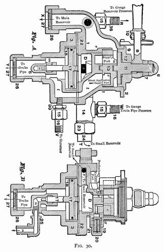
ENGINEER'S BRAKE AND EQUALIZING-DISCHARGE
VALVE.
The purpose of the valve illustrated in Figs. 30 and
31 is to put in the hands of the engineer an apparatus that would
insure a more uniform application of brakes through the entire
length of a long train than was practicable with the old forms
of engineer's valve. It admits of easy and gradual reductions
of air, and prevents the sudden reduction of pressure from the
forward cars that so often led to the release of front brakes
caused by the rush of air through the pipes.
 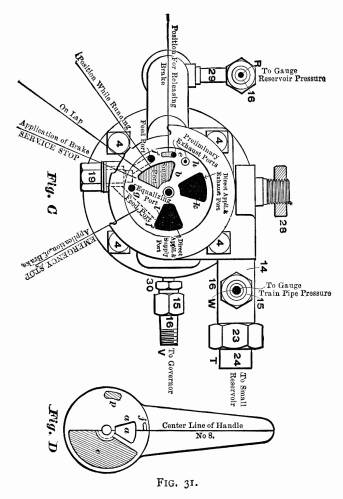
By preparing a diagram similar to Fig. D, representing
the rotary-valve 13 and handle 8, of tracing cloth or other
transparent material, cutting the ports a and j
out of the diagram on their boundary lines to show through
openings, and then reversing same and placing it upon the
seat of the valve, Fig. C, where it may be rotated at will
on its center, the explanation following will be made clear.
By reference to cuts of the valve Figs. 30 and 31, it
will be seen that movement of the handle 8, on which is located
a spring 9 for guiding it to position, operates "rotary valve"
13 upon its seat, opening and closing the various ports
as required.
When the handle 8 is in "position for releasing brake"
air pressure from the main reservoir, entering the brake-valve
at X, passes through "supply ports" a
and b, thence upward into cavity c, in the under
surface of the rotary valve 13, then through "direct application
and supply port" l to the train-pipe at Y.
While yet in this position, port j in the rotary valve
and port e in its seat are in communication, and air passes
into chamber D above piston 17, thence through port
s to a small reservoir, which is usually suspended under
the right running board of the engine, pipe connections being
made therewith at T. This reservoir serves the, purpose
of increased volume of space to chamber D.
The handle 8 now being placed in "position while running,"
direct communication between the train-pipe and main reservoir
ceases, and port j is brought opposite feed-port f
through which main reservoir pressure now passes to the under
side of the "feed-valve" 21, which latter is held to
its seat by "feed-valve spring" 20 having a resistance
of about twenty pounds. When this additional pressure is accumulated
in the main reservoir, "feed-valve" 21 is forced open,
the pressure passing thence through "feed-port" f1
to port l and the train-pipe, while train-pipe pressure
is maintained in chamber D through port l, cavity
c, and "equalizing port" g, thus equalizing
the pressure on top and under piston 17, the stem of which, forming
a valve, is seated in the position shown in "bottom cap"
5, and permits the escape of air from the train-pipe to the atmosphere
through ports m and n when raised from its seat.
When applying brakes for ordinary or station stops, move handle
8 to "on lap" position. This blanks all ports in the
rotary valve and seat. Then moving the valve handle to the position
"application of brake, service stop," the small exhaust
cavity p in the lower surface of the rotary valve 13 establishes
communication between the two "preliminary exhaust ports"
e and h, the latter leading to the atmosphere, and
after discharging about eight pounds pressure as shown by the
gauge, restore the handle to "on lap" position. This
preliminary discharge of air from chamber D will cause
the piston 17 and its stem to rise, which operation is followed
by a discharge of air from the train-pipe to the atmosphere through
ports m and n applying the brakes gently. This discharge
of air from the train-pipe continues after the valve handle is
carried to "on lap" position (gradually equalizing train-pipe
pressure) and until the train-pipe pressure has been reduced slightly
lower than that yet remaining in the chamber above the piston,
when the latter is forced downward, and its stem to its seat,
closing the outlet n, and preventing the further escape
of air, until the operation is repeated, which may be necessary
to apply the brakes with the desired degree of force.
To throw off brakes, push handle 8 to "position for releasing
brakes," causing the excess air-pressure in main reservoir
to be discharged into the train-pipe, insuring their prompt and
certain release.
For an "emergency" application of brakes, push the
handle to the extreme right, to position "application of
brake, emergency stop." This operation establishes direct
communication between the train-pipe and the atmosphere, through
the "direct application and supply port" l, cavity
c, and the "direct application and exhaust port"
k, applying the brakes with full force instantly.
When handling trains on down grades, the handle should be kept
in "full release" position, except when applying brakes,
which will insure the full and prompt recharging of auxiliary
reservoirs under cars.
 PUMP GOVERNOR. PUMP GOVERNOR.
This is an important attachment which ought to be connected to
all air-brake pumps. It not only prevents the carrying of an excessive
air-pressure by the engineers, which often results in the sliding
of the wheels, but it also causes the accumulation of a surplus
of air-pressure in the main reservoir, while the brakes are applied,
which insures the release of the brakes without delay. It also
limits the speed of the pump, and consequently the wear.
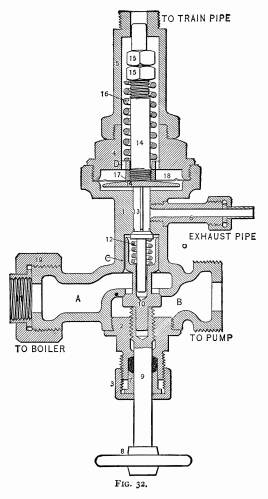
The pump governor is shown in Fig. 32, the object of which
is to automatically cut off the supply of steam to the pump when
the air-pressure in the train-pipe exceeds a certain limit, say
seventy pounds.
The operation of this governor is as follows: the wheel 8 is
screwed down so as to permit the valve 10 to be unseated by the
excess of pressure on the upper side of the valve, permitting
steam to pass through the openings A and B to the
pump. A connection is made from the train-pipe to the upper end
of the governor, and the compressed air passes around the stem
14 to the upper side of the diaphragm plate 18, which is held
to its position by the spring 16, which latter is of sufficient
strength to resist a pressure of, say, seventy pounds per square
inch on diaphragm. As soon as the air-pressure on the diaphragm
18 exceeds this amount, it forces the diaphragm down, unseating
the valve 13, and allowing the steam on the upper side of the
valve 10 to escape through the exhaust 6, which causes an excess
of steam-pressure on the lower side of the valve 10, forcing the
valve against its seat, and cutting off the supply of steam to
the pump.
When the pressure in the train-pipe is diminished by applying
the brakes, the diaphragm is restored to the position shown by
the action of the spring 16. The valve 13 is seated by the spring
12; and the steam pressure, passing through the port C,
accumulates on the upper side of the valve 10, forcing it down,
and opening the passage for steam to the pump until the air-pressure
is again restored to the required limit of seventy pounds.
Table of Contents
| Contents Page
|


