|
THE PROSPECT MOUNTAIN CABLE INCLINE RAILWAY;
LAKE GEORGE, N. Y.
 The latest
addition to inclined railways built in this country for the attraction
and accommodation of tourist traffic is the Prospect Mountain
Incline Railway at Lake George, which was built last winter for
the Horicon Improvement Co. The railway starts from a point near
the terminus of the Delaware & Hudson R. R. at Caldwell, N.
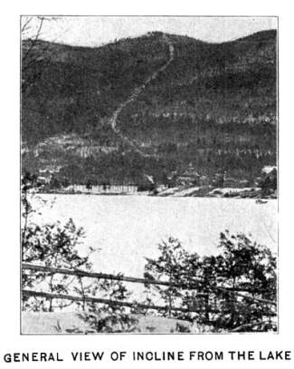
Y., and ascends Prospect Mountain, about 1½ miles west
of that place, rising in 6,625.7 ft. to an elevation of 1,950
ft. above Lake George and 2,250 ft. above sea level. From the
summit of the mountain there is a wide range of view, comprising
the southern peaks of the White Mountains in New Hampshire, the
Green Mountains in Vermont, the Catskill and Adirondack Mountains
in New York, and the Berkshire Hills in Massachusetts. Lake George
is the largest and most easterly of the lakes of the Adirondack
region. It is about 210 miles from New York and 71 miles from
Albany. The lake is 346 ft. above sea level and 247 ft. above
Lake Champlain. The region is a famous summer resort, and is rich
in historical associations; the ruins of Fort George, Fort William
Henry and Fort Ticonderoga serving as reminder, of the early days
when numerous battles were fought here between the French and
English armies and the Indians. The names of Generals Abercrombie,
Howe and Burgoyne, of the English armies, and General Montcalm,
of the French army, are associated with the military history of
the region. The latest
addition to inclined railways built in this country for the attraction
and accommodation of tourist traffic is the Prospect Mountain
Incline Railway at Lake George, which was built last winter for
the Horicon Improvement Co. The railway starts from a point near
the terminus of the Delaware & Hudson R. R. at Caldwell, N.
Y., and ascends Prospect Mountain, about 1½ miles west
of that place, rising in 6,625.7 ft. to an elevation of 1,950
ft. above Lake George and 2,250 ft. above sea level. From the
summit of the mountain there is a wide range of view, comprising
the southern peaks of the White Mountains in New Hampshire, the
Green Mountains in Vermont, the Catskill and Adirondack Mountains
in New York, and the Berkshire Hills in Massachusetts. Lake George
is the largest and most easterly of the lakes of the Adirondack
region. It is about 210 miles from New York and 71 miles from
Albany. The lake is 346 ft. above sea level and 247 ft. above
Lake Champlain. The region is a famous summer resort, and is rich
in historical associations; the ruins of Fort George, Fort William
Henry and Fort Ticonderoga serving as reminder, of the early days
when numerous battles were fought here between the French and
English armies and the Indians. The names of Generals Abercrombie,
Howe and Burgoyne, of the English armies, and General Montcalm,
of the French army, are associated with the military history of
the region.
The old Lake House, at the summit of Prospect Mountain, was
bought last year by Mr. Wm. M. Peck, of Glens Falls, N. Y., who
has made considerable improvements and extensions, and the railway
and hotel are owned by the Horicon Improvement Co., of which Mr.
Peck is President and Mr. A. B. Colvin, of Albany, N. Y., State
Treasurer, is a director. Construction of the railway was commenced
on Jan. 2, 1895, and was carried on through many difficulties
incident to the cold and snow. The first car was run on June 2
and the road was opened to traffic on June 15. The total cost
was about $120,000.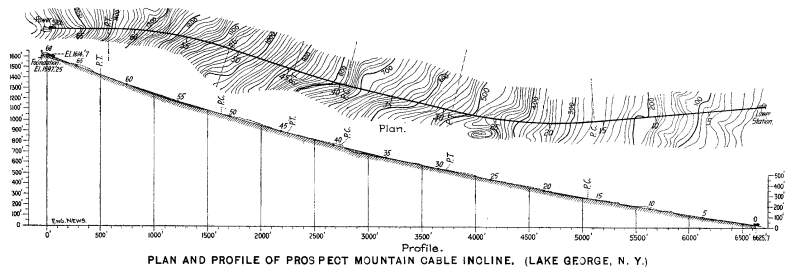
The length of the line, measured on a level, is 6,625.7 ft., and
the total rise is 1,594.7 ft., the length measured on the grade
of the incline being 6,780 ft. The average grade is 24%, the maximum
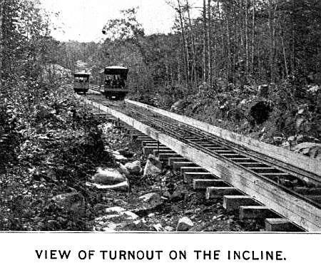
grade being 37.8% and the minimum 13½%. The alinement,
commencing at the lower station and not including the turnout
curves at the middle, is about as follows:
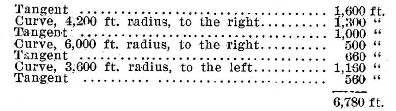 The line has a
single track of 3-ft. gage, with a four-rail turnout on passing
place at the middle. The rails weigh 35 lbs. per yd., and are
spiked to ties 6 x 6 ins. and 8 ft. long, spaced about 24 ins.
c. to c. The joints are supported, spliced by plain fishplates,
and the ends of the rail base are notched for spikes to prevent
creeping. On each side of the track is a yellow pine guard rail,
6 x 8 ins., built up of two timbers 6 x 4 ins., laid to break-joints
and bolted with mushroom headed bolts at each tic. These guard
timbers are embraced by the Otis double-grip safety brake, which
is applied automatically in case of the car getting beyond control,
or can be applied by hand in case of emergency. The ties rest
upon longitudinal timbers, 6 x 10 ins., which are bolted to mudsills
spaced 6 ft. 8 ins. apart, or 4 ft. apart under the joints of
the stringers. The line is in cut and fill, with the exception
of four trestles. On the lower half of the line the excavation
is mainly in earth and hardpan, while on the upper part the excavation
is in granite. The four trestles aggregate 1,400 ft. in length,
and have a maximum height of about 25 ft. They are built of native
hemlock, except that the stringers are of Southern yellow pine,
and the construction closely resembles that used on the Catskill
Mountain cable incline, shown in our issue of Aug. 18, 1892. The
bents are 16 ft. apart, and are built up of two plumb-posts 10
x 10 ins. and two batter-posts 8 x 10 ins., formed into sills
10 x 10 ins., and caps 10 x 10 ins. x 8 ft. The transverse diagonal
bracing is of planks, 2½ x 8 ins., spiked to the caps and
sills, and longitudinal diagonal bracing is placed between some
of the bents. There are also longitudinal timbers, 4 x 8 ins.,
bolted to the inside of the bottom of the plumb-posts. Under each
rail are two stringers 6 x 14 ins. on edge, laid to break-joint,
and separated by 2-in. thimbles, and these stringers rest on corbels
6 x 12 ins., 3 ft. long, notched onto the caps, to give the proper
inclination for the stringer bearings. The ties are 6 x 6 ins.,
18 ins. apart in the clear. They are 13 ft. long, carrying a 42-in.
footway on one side, protected by a wooden railing 4 ft. high. The line has a
single track of 3-ft. gage, with a four-rail turnout on passing
place at the middle. The rails weigh 35 lbs. per yd., and are
spiked to ties 6 x 6 ins. and 8 ft. long, spaced about 24 ins.
c. to c. The joints are supported, spliced by plain fishplates,
and the ends of the rail base are notched for spikes to prevent
creeping. On each side of the track is a yellow pine guard rail,
6 x 8 ins., built up of two timbers 6 x 4 ins., laid to break-joints
and bolted with mushroom headed bolts at each tic. These guard
timbers are embraced by the Otis double-grip safety brake, which
is applied automatically in case of the car getting beyond control,
or can be applied by hand in case of emergency. The ties rest
upon longitudinal timbers, 6 x 10 ins., which are bolted to mudsills
spaced 6 ft. 8 ins. apart, or 4 ft. apart under the joints of
the stringers. The line is in cut and fill, with the exception
of four trestles. On the lower half of the line the excavation
is mainly in earth and hardpan, while on the upper part the excavation
is in granite. The four trestles aggregate 1,400 ft. in length,
and have a maximum height of about 25 ft. They are built of native
hemlock, except that the stringers are of Southern yellow pine,
and the construction closely resembles that used on the Catskill
Mountain cable incline, shown in our issue of Aug. 18, 1892. The
bents are 16 ft. apart, and are built up of two plumb-posts 10
x 10 ins. and two batter-posts 8 x 10 ins., formed into sills
10 x 10 ins., and caps 10 x 10 ins. x 8 ft. The transverse diagonal
bracing is of planks, 2½ x 8 ins., spiked to the caps and
sills, and longitudinal diagonal bracing is placed between some
of the bents. There are also longitudinal timbers, 4 x 8 ins.,
bolted to the inside of the bottom of the plumb-posts. Under each
rail are two stringers 6 x 14 ins. on edge, laid to break-joint,
and separated by 2-in. thimbles, and these stringers rest on corbels
6 x 12 ins., 3 ft. long, notched onto the caps, to give the proper
inclination for the stringer bearings. The ties are 6 x 6 ins.,
18 ins. apart in the clear. They are 13 ft. long, carrying a 42-in.
footway on one side, protected by a wooden railing 4 ft. high.
 The work was laid
out entirely by measurements parallel to the grade line, so that
the difference of elevation at any two stations is the sine of
the angle of the slope at that point, the horizontal distance
being the cosine. The contours on the topographical plan accompanying
the profile represent, therefore, not a vertical projection, as
in ordinary practice, but a development of the topography by rolling
out on the grade line. This method is said to, have greatly facilitated
the calculations of grade and power required. The grades are so
adjusted that the two trains with average loads, and including
the weight of the cable, balance each other at all points of line.
The curvature of the grade is not continuously convex downward,
but is flattened for a short distance near the turnout by means
of a curve convex upward, making a slight reverse curve in the
profile. The calculations for balancing grades were made for cars
weighing 14,000 lbs., carrying 27 passengers at 150 lbs. each
(or 18,050 lbs. at each end of the cable), and a cable weighing
2½ lbs. per ft. The work was laid
out entirely by measurements parallel to the grade line, so that
the difference of elevation at any two stations is the sine of
the angle of the slope at that point, the horizontal distance
being the cosine. The contours on the topographical plan accompanying
the profile represent, therefore, not a vertical projection, as
in ordinary practice, but a development of the topography by rolling
out on the grade line. This method is said to, have greatly facilitated
the calculations of grade and power required. The grades are so
adjusted that the two trains with average loads, and including
the weight of the cable, balance each other at all points of line.
The curvature of the grade is not continuously convex downward,
but is flattened for a short distance near the turnout by means
of a curve convex upward, making a slight reverse curve in the
profile. The calculations for balancing grades were made for cars
weighing 14,000 lbs., carrying 27 passengers at 150 lbs. each
(or 18,050 lbs. at each end of the cable), and a cable weighing
2½ lbs. per ft.
The cable is 1¼ ins. diameter, weighing 2.528 lbs. per
ft., and is 7,150 ft. long, making four wraps on the winding drums.
The ends of the cable are attached to the downhill side of the
car frames, the cable passing under a saddle at the front of the
car, which holds it down to within a few inches of the idler pulleys.
These pulleys are of cast iron, 12 ins. diameter (to center of
cable) on the tangents and 15 ins. on the curves, the latter being
inclined towards the center of the curve and having a very high
flange on the outer side. The pulleys are set 30 ft. apart, those
for the ascending and descending cable being set two tie spaces
apart, in order to provide room for the boxes and bearings. The
pulley bearings run in babbitted boxes, and these boxes are supported
by wrought iron straps bent to shape and fastened to the ties
by lag screws. At the turnout the cable, which is normally above
the rails, passes through a slot in the rails, dropping into the
slot by its own weight and being guided by special pulleys for
this purpose The turnout is operated automatically.
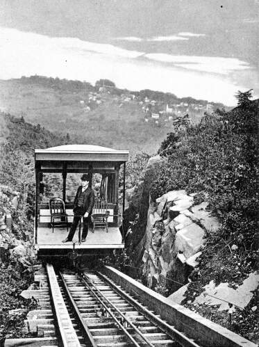
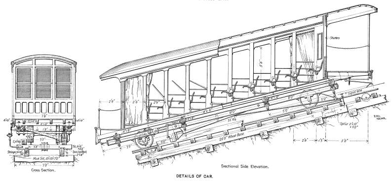
The cars are open, with canvas side curtains for use in bad
weather, and have nine transverse seats; the seats being so set
as to be horizontal on the grade. Each car is about 32 ft. long
and 7 ft. 6 ins. wide, weighs a little over 13,000 lbs., and has
seating accommodations for 54 passengers while 80 or 90 persons
can be accommodated by standing. The front platform is of extra
length, and is intended to carry freight and baggage. The car
frame is of channel iron, and each car is carried on four 24-In.
wheels, the wheelbase being 20 ft. The wheels on one side (on
the outer rail) are double-flanged, or grooved, while those on
 the other side are
flat, 8 ins. wide, in order to pass over the turnout, the flat
wheel passing over the slot through which the cable drops, as
above described. There is telephone communication between the
cars and the power house, a copper signal wire being supported
on iron standards attached to the ends of the ties, as shown,
each car having a wire loop contact piece attached to the end
of a vertical rod and held down upon the line wire by a spring.
This wire contact replaces a grooved contact wheel, which was
found to be liable to jump off the wire. Each car is also fitted
with the necessary equipment of batteries, telephone and signal
bell, and there is a code of bell signals for starting and stopping.
The running speed is 850 ft. per minute, or about 10 miles per
hour and the trip occupies about eight minutes on the average. the other side are
flat, 8 ins. wide, in order to pass over the turnout, the flat
wheel passing over the slot through which the cable drops, as
above described. There is telephone communication between the
cars and the power house, a copper signal wire being supported
on iron standards attached to the ends of the ties, as shown,
each car having a wire loop contact piece attached to the end
of a vertical rod and held down upon the line wire by a spring.
This wire contact replaces a grooved contact wheel, which was
found to be liable to jump off the wire. Each car is also fitted
with the necessary equipment of batteries, telephone and signal
bell, and there is a code of bell signals for starting and stopping.
The running speed is 850 ft. per minute, or about 10 miles per
hour and the trip occupies about eight minutes on the average.
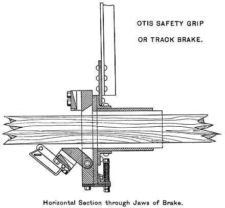
The safety grip consists of a heavy steel plate embracing the
guard timber and resting against a butting frame of plates and
angles, forming part of the car frame. A hinged dog is attached
to the grip plate, and lies on the inner side of the guard timber.
Both plate and dog have chiseled edges and are fitted with toothed
plates. The hinged dog is held away from contact with the guard
timber by a weighted lever having a vertical leg, whose end rests
in the notch of a latch carried by a shaft, which is fitted with
a pawl opposite the speed governor of the car axle. The main grip
plate is held away from contact with the guard timber by a brass
spring. The governor itself is similar in operation to the ball
governor of a steam engine, but the balls are replaced with heavy
plates, or jaws, having lugs or teeth formed on the outer edges.
When the car attains excessive speed in descending, the plates
fly out far enough to bring the teeth in contact with the pawl,
thus releasing the latch and causing the weighted lever to drop,
forcing the toothed dog and grip into the guard timber to a depth
of about three-eigths in. on each side. The resisting power of
this safety grip, acting on a yellow pine guard rail, has been
found by experiment to be 28,000 lbs. The governor is set to act
at a speed of 14 miles per hour. To release the grip, the motion
of the car is reversed, so as to relieve the strain on the grip,
and the conductor then pulls up the lever and sets it in the latch,
after which the car can go ahead again. As the car must be drawn
back before the grip can be released, it is evident that the conductor
cannot release it unless the cable is intact. If from any cause
the car should get beyond control, the conductor can apply the
safety grip, throwing the latch by means of the handle shown in
front of the dashboard, without waiting for the car to attain
sufficient speed to cause the governor to apply the brake.
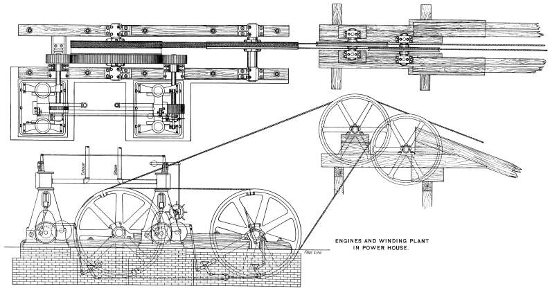
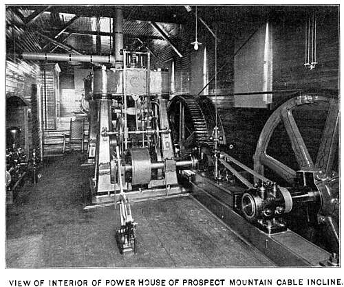 The hoisting plant
is contained in a power house at the upper end of the incline.
It consists of two Otis vertical inverted compound engines of
the marine type, with cylinders 8 x 10 and 12 x 10 ins., and running
at about 200 revolutions per minute. The exhaust of one engine
is used in the low-pressure cylinder of the other, and valves
are arranged in the steam pipes so that both engines can take
live steam direct from the boilers in case of extra heavy loads,
but this has not been necessary so far, as the engines are found
to be capable of doing all the work required when working as compounds.
They develop about 90 HP. when working compound, and can develop
up to 200 HP. when working simple. Each engine drives a pinion
23 ins. diameter, the pinions being on opposite sides of the main
spur wheel, which has a diameter of 8 ft. on the pitch line, a
face 9 ins. wide, and teeth set at a pitch of about 2½
ins. The shaft of this wheel drives two cast iron drums 8 ft.
diameter, one being an idler and the other a driving wheel, and
the cable makes four turns round these drums. The engines are
provided with a hand brake, and also with an emergency brake acting
on the main driving drum, but there has been no necessity for
the use of either of these brakes as yet, the working being completely
controlled by the use of the steam valves. Steam is supplied by
a Heine water-tube boiler of 200 HP., built by the Heine Safety
Water Tube Boiler Co., of St. Louis, Mo., and this boiler also
supplies steam for the electric plant for lighting the stations
and hotels connected with the plant. The current is generated
by a Westinghouse alternating dynamo, with a capacity for 1,100
lights of 16 c. p. There are converters at top and bottom of the
incline. The water is taken from a mountain brook and pumped up
into tanks of 12,000 gallons capacity at the power house by a
special boiler and pump placed in the Valley to the west of the
summit, at a point about 4,000 ft. distant from, and 600 ft. below,
the summit. The supply of water is also used for the hotels and
other buildings. The hoisting plant
is contained in a power house at the upper end of the incline.
It consists of two Otis vertical inverted compound engines of
the marine type, with cylinders 8 x 10 and 12 x 10 ins., and running
at about 200 revolutions per minute. The exhaust of one engine
is used in the low-pressure cylinder of the other, and valves
are arranged in the steam pipes so that both engines can take
live steam direct from the boilers in case of extra heavy loads,
but this has not been necessary so far, as the engines are found
to be capable of doing all the work required when working as compounds.
They develop about 90 HP. when working compound, and can develop
up to 200 HP. when working simple. Each engine drives a pinion
23 ins. diameter, the pinions being on opposite sides of the main
spur wheel, which has a diameter of 8 ft. on the pitch line, a
face 9 ins. wide, and teeth set at a pitch of about 2½
ins. The shaft of this wheel drives two cast iron drums 8 ft.
diameter, one being an idler and the other a driving wheel, and
the cable makes four turns round these drums. The engines are
provided with a hand brake, and also with an emergency brake acting
on the main driving drum, but there has been no necessity for
the use of either of these brakes as yet, the working being completely
controlled by the use of the steam valves. Steam is supplied by
a Heine water-tube boiler of 200 HP., built by the Heine Safety
Water Tube Boiler Co., of St. Louis, Mo., and this boiler also
supplies steam for the electric plant for lighting the stations
and hotels connected with the plant. The current is generated
by a Westinghouse alternating dynamo, with a capacity for 1,100
lights of 16 c. p. There are converters at top and bottom of the
incline. The water is taken from a mountain brook and pumped up
into tanks of 12,000 gallons capacity at the power house by a
special boiler and pump placed in the Valley to the west of the
summit, at a point about 4,000 ft. distant from, and 600 ft. below,
the summit. The supply of water is also used for the hotels and
other buildings.
The road was designed and built for the Horicon Improvement Co.,
by the Otis Engineering & Construction Co., of New York city,
and the operating plant was designed by Mr. Thomas E. Brown, Jr.,
M. Am. Soc. C. E., Chief Engineer and Manager of the latter company,
to whom we are indebted for drawings and particulars used in preparing
this article. Mr. C. F. Parker was the Resident Engineer. The
grading trestles and trackwork were sublet to Mairs & Lewis,
of New York city. The engines, safety devices, etc., were furnished
by Otis Brothers & Co., of New York city, and the winding
drums, pulleys, cars and frog and switch equipment by the Ramapo
Iron Works, of Hillburn, N. Y. The cable, which is of the Lang-Lay
pattern, was made by the John A. Roebling's Sons Co., of Trenton,
N. J. The electric lighting plant was furnished by Westinghouse,
Church, Kerr & Co., of New York city.
Stories Page | Contents Page
|


