RACK RAILWAY LOCOMOTIVE.
Scientific American Supplement, No.
70—May 5, 1877
THE Kahlenberg, near Vienna, is a mountain which rises abruptly
from the banks of the Danube, and which, on account of the splendid
views to be seen from the summit, is a great resort of holiday
seekers. A rope railway was opened in 1873, and it ascends the
mountain on the northwestern side, it being, in fact, situated
on the flank of the Leopoldsberg and not of the Kaldenberg proper.
At the same time that this rope railway was projected. another
company was also started for constructing a second line ascending
the Kahlenberg on the eastern side, this second railway being
considerably longer and having much flatter gradients than its
rival, while instead of being worked by a rope, it is provided
with a central rack on the plan introduced on the Mount Washington
Railway and subsequently adopted with so much success on the Rigi.
It is a locomotive for this second line which forms the subject
of our present engravings.
The line, which has a gauge of 4 ft. 8½ in., commences
at Nussdorf, the first station from Vienna on the Franz-Josef
Railway, and it passes through Grinzing and Krapfenwald to the
summit of the Kahlenberg, its gradients being successively 1 in
25, 1 in 12½, 1 in 20, 1 in 10, 1 in 33, 1 in 10, and 1
in 33. The line, it will be seen, is very much less steep than
the Rigi Railway. The line is laid with rails weighing 20 kils.
per metre, or about 40 lbs. per yard, while between the rails,
and securely fixed to the sleepers, is the rack, composed of two
2.4 in. by 4 in channel irons with wrought iron teeth between
them, these teeth being of 4 in. pitch. The rack is constructed
very similarly to that of the Rigi Railway already described in
our pages, and it weighs 55 kils. per metre, or about 110 lbs.
per yard.
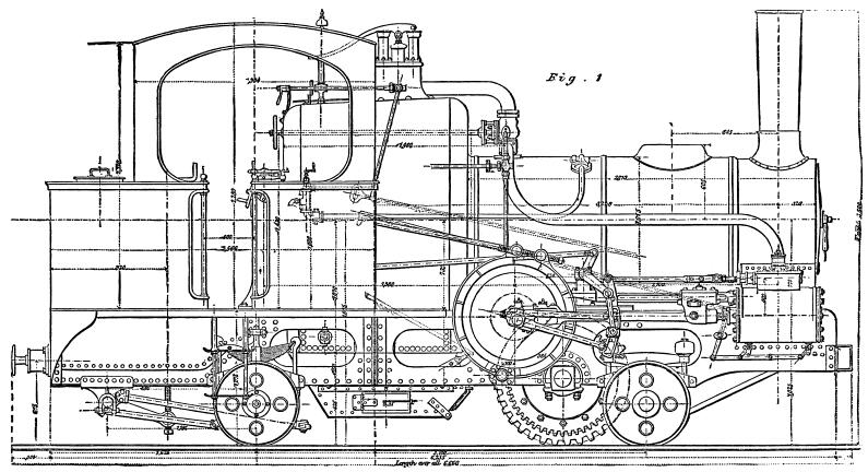
The locomotives for working the lines are built by the Schweizerische
Locomotiv and Maschinen-Fabrik of Winterthur, of which works Mr.
Charles Brown is the manager, and their general design will be
readily understood from our engravings. The engine, we may remark,
goes up the line at the tail of its train, the carriages being
pushed before it, while in going up the hind end goes first, the
chimney end being always lowest. A dotted line in Fig. 2 shows the level of the water when
the engine is going up an incline of 1 in 10.
The boiler is of the ordinary locomotive type, but it has an
exceptionally high firebox casing, the top of this casing and
the crown of the firebox sloping downward towards the hind end,
as shown. The barrel is so placed with regard to the firebox that
it is full of water when the latter is at the proper level. A
diaphragm plate is fixed across the barrel above the tubes, as
shown in Fig. 2 and Fig.
5, so as to divide the ascending and descending currents.
The firebox is 3 ft. 11¼ in. long, 2 ft. 9 in. wide, and
4 ft. 4½ in. high at the center, the heating surface it
exposes being 65.3 square feet. The barrel contains 174 tubes,
1.417 in. inside and 1.575 in. outside diameter, and 7 ft. ¾
in. long, the heating surface exposed by them being 506.6 square
feet, making the total heating surface 571.9 square feet. The
grate area is 10.6 square feet. The arrangement of the boiler
stays and of the steam pipes and regulator will be understood
from the engraving.
The cylinders are 13 in. in diameter, while the pistons have
a stroke of 17.72 in., and are fixed outside, as shown, the connecting
rods, taking hold of pins on cranks disks at the ends of a strong
shaft which extends across the engine in front of the firebox.
One of the crank disks—that on the right hand side—is
fitted with a powerful brake, as shown in Fig. 1 and
Fig. 3.
On the crank shaft are keyed two pinions with 23 teeth of 2 in.
pitch, which gear into wheels with 55 teeth on a second motion
shaft, as shown in Fig. 3. Between
the two wheels just mentioned is securely bolted the wheel gearing
into the rack, this wheel having 35 teeth of 4 in. pitch, and
the diameter on the pitch line being 41.36 in. Owing to the proportions
of the gearing the crank shaft makes 2.391 revolutions for each
revolution of the rack wheel, and the tractive power exerted by
the engine for each pound of effective pressure on the piston
is thus:
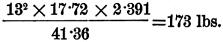
As the boiler is worked at 9 atmospheres, or 132 lbs. per square
inch, a tractive—or under the circumstances rather a pushing—force
of fully 18,000 lbs. Can be exerted when required.
The general arrangement of the working gear is shown clearly
in Fig. 1 and Fig. 3, and will
require no special explanation; we may remark, however, that when
descending with a train the engine is run in back gear and a kind
of cock or valve with which the exhaust pipe is fitted is then
turned so that the cylinders take in pure air and not dust and
ashes from the smoke box. The arrangement of this valve and the
gear for working it are shown in Fig.
2, Fig. 3, and Fig. 5. The air compressed by the action
of the pistons when the engine is thus running reversed is not
discharged into the boiler (the regulator being closed), but is
allowed to escape through the air cock, the opening of which is
adjustable by the driver.
The engine is carried on two pair of wheels, the center of
axles being 10 ft. 2 in. apart. The leading wheels are fixed on
their axle in the usual way, and the weight is transmitted to
their axle boxes through india rubber springs. The trailing wheels,
on the other hand, run free on their axle, the latter carrying
a strong spur wheel gearing into the rack and also a pair of grooved
drums fitted with a powerful brake. This arrangement is best shown
in Fig. 2 and Fig.
4. It will be seen from the above description that three modes
of checking the engine and train are provided, namely, the brakes
on the trailing axle and crankshaft and the running of the engine
in reverse gear. By these means a most perfect control of the
engine and train is maintained during the descending journey.
The engine is strongly framed, and a water tank containing
220 gallons of water is provided between the frames at the hind
end, while a small supplementary tank above contains 19.8 gallons
more. The coal box is at the back of the foot-plate, and contains
25 cwt. The weight of the engine empty is 15.76 tons, or in full
working order 19.44 tons, while the load taken up consists of
three carriages weighing 32½ tons empty; or about 42 tons
when full of passengers. Altogether the locomotive is a great
improvement on those with vertical boilers used on the Rigi Railway,
and, as in all engines constructed under Mr. Brown's directions,
the details are well worked out.—Engineering.
Mountain RR
| Contents Page
|


