Curiosities of Locomotive
Design.*
*From Development of the Locomotive Engine, by Angus Sinclair.
Railway and Locomotive Engineering—September-December, 1907
The Enterprising Inventor.
The man who ventures to stray from the familiar beaten path
may stumble into a quagmire, but he may have the good fortune
to discover a vein of rich ore which the beaten path would never
reveal.
When an inventor scorning the common forms proceeds to work
out new and original shapes for himself, he may produce something
which is ridiculous and impracticable, but even when he does that,
the enterprising person deserves praise, for it has been by departing
from other people's lead that new and original inventions have
been given to the world.
 In publishing
a chapter on Freaks and Curiosities in Locomotive Designs it is
not done in a spirit of levity, but to give a record of well meaning
inventions that did not perform the functions the inventors expected. In publishing
a chapter on Freaks and Curiosities in Locomotive Designs it is
not done in a spirit of levity, but to give a record of well meaning
inventions that did not perform the functions the inventors expected.
For the first twenty years after Trevithick built his locomotive,
a belief was common that plain wheels would not adhere to the
rail with sufficient tenacity to induce propulsion. It had happened
that Trevithick's engine was what has become known as over-cylindered,
the effect being that the engine was furiously slippery. Other
pioneer locomotives suffered from the same defect and remedies
were invented which now appear to be ridiculous.
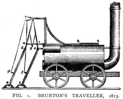
The Mechanical Traveler.
The most notable invention of this kind is illustrated, Fig.
1, and was known as Brunton's Mechanical Traveller. Brunton was
aware that the action of the horse up to that time had been the
most successful means of hauling vehicles, and the question arose,
why not utilize the action of the horse mechanically? The engine
was duly built to put that idea in practice. It had a horizontal
boiler and a single cylinder set on top with piston connecting
with levers that acted the part of a horse's legs.
 The
invention excited much attention. It had the merit of acting as
the designer intended it should, and one day that it was on trial,
rushing along at a speed of three miles an hour, accompanied by
a host of admirers, the boiler exploded, throwing hot water, pieces
of iron, and disaster among the crowd. That ended the career of
the Mechanical Traveller. The
invention excited much attention. It had the merit of acting as
the designer intended it should, and one day that it was on trial,
rushing along at a speed of three miles an hour, accompanied by
a host of admirers, the boiler exploded, throwing hot water, pieces
of iron, and disaster among the crowd. That ended the career of
the Mechanical Traveller.
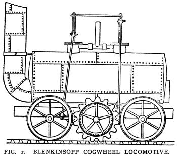
Cog Wheel Locomotive.
The first attempt to overcome the deficient adhesion of plain
iron wheels on plain iron rails was made in 1811, by J. Blenkinsopp,
who obtained a patent for a self propelling steam engine, Fig.
2, worked by a cog wheel engaging a rack rail, a practice now
common on mountain railways.
This Blenkinsopp engine was the first locomotive to perform
profitable traction work. It was well designed for the time, having
two cylinders 8 x 20 inches, set partly into the boiler and transmitting
power to right angle cranks which drove the toothed driving wheels.
A sensible feature about this engine was that the piston crossheads
worked in guides instead of being controlled by parallel motion,
as the pistons of most early locomotives were. The engine was
used for about twenty years.
 Tentative
Evolution. Tentative
Evolution.
In the course of evolution a variety of locomotives were built
resembling Hedley's Puffing Billy, but they followed the line
of improvement that led to the Rocket in 1829, which established
the elements of a permanent type. In Great Britain there were
not many departures from the foundation form of the Rocket.
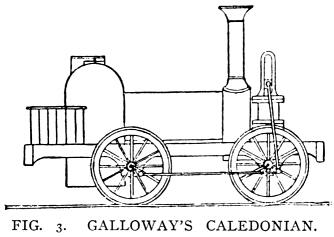
An engine called the "Caledonian," Fig. 3, was bought
by the Liverpool and Manchester in 1832. The vertical cylinders
were secured in front of the smoke box, with pistons working through
the upper cover to connecting rods that extended down to the driving
wheels. That engine displayed a weakness for jumping the track,
and was changed after a few months of service. Its only service
to railways was emphasizing the mistake of using vertical cylinders.
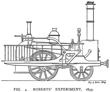 Roberts'
Bell-Crank Locomotive. Roberts'
Bell-Crank Locomotive.
About the same time Richard Roberts, who afterwards became
a noted locomotive builder, brought out what he called the "Experiment,"
Fig. 4. That engine had vertical cylinders operating bell cranks
which drove rods connecting with crank pins outside of the driving
wheels. This engine had piston valves. It was used only for a
few months.
Similar locomotives were built for the Dundee and Newtyle Railway,
in Scotland, one called the "Earl of Airlie," having
attracted considerable attention, which did not save it from alteration
after a short career.
The bell-crank method of transmitting power to the driving
wheels has been used' successfully for special forms of locomotives
in which it was not convenient to transmit the power direct. The
real difficulty with Roberts' engines and those made for the Newtyle
Railway seems to have been in the piston valves, which were crude
devices.
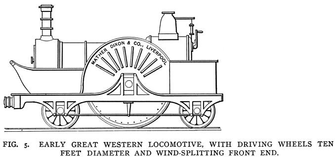
Immense Driving Wheels.
Isambard Brunel, chief engineer of the Great Western, Railway,
of England, who made the gauge of that railway seven feet wide,
had a predilection for large sizes, among them large driving wheels.
An engine shown in Fig. 5 had driving wheels 10 feet in diameter.
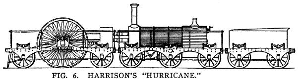
About the time that engine was built the Great Western Railway
received one of the kind shown in Fig. 6. The latter was made
according to the Harrison patent, which called for driving wheels
being secured on one set of frames, the boiler being carried on
another set. The science of mechanical engineering was in its
infancy in those days, yet one marvels how the designer of such
a locomotive expected to obtain the necessary adhesion.
A similar engineering blunder was made a few years later in
the United States, when G. A. Nichols, superintendent of the Philadelphia
& Reading Railroad, had a locomotive built with the boiler
carried on a frame separate from the engine. Mr. Nichols' idea
was fairly rational, however, for he was trying to make a boiler
with grate surface sufficiently large to burn anthracite coal.
Harrison departed from prevailing practice in order to apply abnormally
large driving wheels.
The inclination to use huge driving wheels was based on the
fallacy that the size of the driving wheels measured the speed
possibilities of a locomotive. It took years of experience to
demonstrate that the boiler was really what controlled the speed.
Some of the high wheel Crampton locomotives, built in Europe and
in the United States about 1850, had the boilers so small that
want of steam reduced the speed before the train had gone five
miles, when high speed was attempted.
 Indirect
Driving. Indirect
Driving.
Although it is a recognized physical axiom that in locomotive
engineering a pull or thrust is most effective when worked horizontally,
the fallacy of vertical or inclined cylinders influenced the design
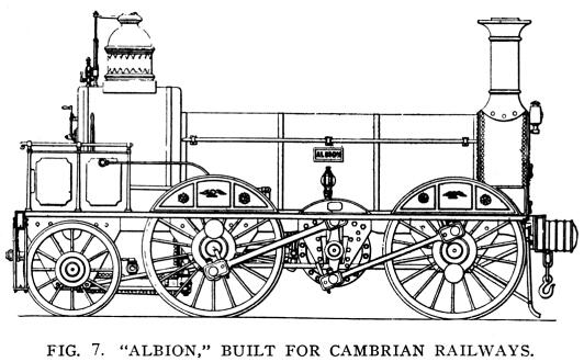
of locomotives for many years. Many attempts were made to increase
power by means of intermediate driving axle arrangements of the
type illustrated in Fig. 7. A very interesting attempt of this
kind is illustrated in "Sekons Evolution of the Steam Locomotive."
This engine was built at Bradford, England, for the Cambrian Railway.
It was a vibratory engine, the special merit claimed for the arrangement
of mechanism being that it produced perfect balance of the reciprocating
and revolving parts. I wonder that the hammer blow alarmist never
tried this engine.
The driving axle was secured between the frames and set parallel
to the wheel axles. The driving axle was secured at each end to
a strong disk which held power transmitting mechanism. The pistons,
which were fan shaped, drove rocking shafts secured to the driving
axle and it in turn vibrated the disks to which the main rods
were secured.
It was an ingenious engine, and is reported to have done good
service on small cost for fuel and repairs.
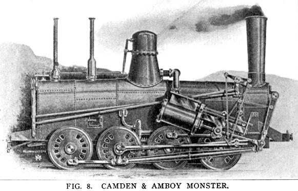
Locomotives driven through a supplementary driving axle were
very common in the United States, but they were used mostly in
the process of evolution. All the Baltimore & Ohio grasshopper
engines were driven in this way and they worked quite satisfactorily.
The Camden & Amboy monster, shown in Fig. 8, had heavy spur
gears on the axles of the middle pairs of wheels which engaged
with an intermediate gear performing part of the work done by
coupling rods.
 When locomotives
of that character have been built by men seeking for the best
form of engine to perform the work of train hauling, their efforts
were commendable, but at various times amateur locomotive designers,
saturated with egotism and personal conceit, have produced ridiculous
engines and sometimes their friends have tried to force them into
use through stock-selling operations. A notable case of this character
was the Raub Central Power locomotive, Fig. 9, built at Paterson,
N. J., in 1892. The people interested in this invention tried
to push it through the influence of sensational articles in the
daily newspapers, their claims for speed and efficiency being
senseless exaggerations, but their efforts were in vain. As usual,
they blamed its unpopularity upon the prejudice of railroad men
and the engineering press. The engine had two small boilers, each
with a fire door on each side and a smoke flue going back to the
stack in the centre. When locomotives
of that character have been built by men seeking for the best
form of engine to perform the work of train hauling, their efforts
were commendable, but at various times amateur locomotive designers,
saturated with egotism and personal conceit, have produced ridiculous
engines and sometimes their friends have tried to force them into
use through stock-selling operations. A notable case of this character
was the Raub Central Power locomotive, Fig. 9, built at Paterson,
N. J., in 1892. The people interested in this invention tried
to push it through the influence of sensational articles in the
daily newspapers, their claims for speed and efficiency being
senseless exaggerations, but their efforts were in vain. As usual,
they blamed its unpopularity upon the prejudice of railroad men
and the engineering press. The engine had two small boilers, each
with a fire door on each side and a smoke flue going back to the
stack in the centre.
Vertical cylinders were employed, transmitting the power through
a central shaft. This engine was not only an oddity, it was a
fake of the worst kind. Instead of an advance in design, it was
returning to pioneer practices, being a product of combined ignorance,
egotism and perversity.
Ever since people became inventors of mechanical appliances,
there have been persistent attempts made to overcome the laws
of nature by arrangements of mechanism designed to produce perpetual
motion. In some instances inventors labored to produce apparatus
that would maintain motion of their own unaided volition, others
labored by combinations of mechanism to gain power by leverages
or their equivalents.
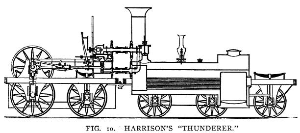 Of this class
of invention was the Harrison locomotive, shown in Fig. 10. In
this engine the real driving wheels, which had geared peripheries
engaged with cogs on the rail wheel axle. The expectation was
that excessive speed could be maintained with reduced expenditure
of power, as the piston speed could be regulated at what the engineers
of the time considered most conducive to economy of steam. The
engine shown was built by Hawthorns of Newcastle, in 1837, the
gearing being 3 to 1, so that one revolution of the driving wheels
caused the rail wheel to turn three times. The "Hurricane"
was used a short time on the Great Western Railway, and was said
to have maintained a speed of 100 miles an hour, but that did
not preserve it from premature demise. Harrison's failure did
not discourage others, from trying similar experiments. Of this class
of invention was the Harrison locomotive, shown in Fig. 10. In
this engine the real driving wheels, which had geared peripheries
engaged with cogs on the rail wheel axle. The expectation was
that excessive speed could be maintained with reduced expenditure
of power, as the piston speed could be regulated at what the engineers
of the time considered most conducive to economy of steam. The
engine shown was built by Hawthorns of Newcastle, in 1837, the
gearing being 3 to 1, so that one revolution of the driving wheels
caused the rail wheel to turn three times. The "Hurricane"
was used a short time on the Great Western Railway, and was said
to have maintained a speed of 100 miles an hour, but that did
not preserve it from premature demise. Harrison's failure did
not discourage others, from trying similar experiments.
The inventive habit has been cultivated for many years in the
United States through liberal patent laws that enable an inventor
to enjoy the fruits of his ingenuity. Owing to this there is an
army of ingenious men ever ready to improve on foreign inventions,
with the result that a mechanical oddity appearing in a foreign
country soon appears on this side of the Atlantic in exaggerated
form. The Harrison two-story locomotives had several imitations
in America.
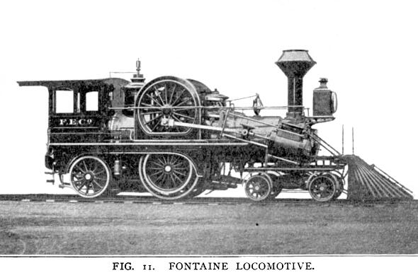 The Fontaine
Freak. The Fontaine
Freak.
In 1881 the Grant Locomotive Works, of Paterson, N. J., built
a locomotive, Fig. 11, designed by Eugene Fontaine, of Detroit,
which excited great attention for a few years owing to the radical
departure from established practice in designing locomotives.
Fontaine built his engine with the driving wheels above the boiler,
so arranged that their tread pressed upon and transmitted motion
to the carrying wheels by frictional contact. The reasons given
by the designer for building this form of an engine were: "The
question of faster speed in railroad travel is one that is now
attracting attention on the part of the public, who demand it,
and of the railroads, who are anxious to meet the demand.
"It is well known that to increase speed in locomotives,
as now used, beyond a certain rate, can only be done by an increase
of steam pressure, which can only be obtained by increased expenditure
of fuel, and such an expense increases in a tenfold ratio to the
increased rate of speed obtained, to say nothing about the additional
strain upon the boiler."
To overcome these imaginary deficiencies the locomotive with
two driving wheels set up in the air above two other driving wheels
that rested on the rail was built and put in service. There was
considerable discussion on the invention, but there were very
few engineers who believed that any advantage of steam or economy
could be secured by the wheel arrangement adopted. Their judgment
was vindicated by the results of practical service. The engine
was tried on all kinds of trains, but proved inferior in every
respect to the ordinary engines of the same capacity. The engine
was examined as a curiosity in a variety of roundhouses for a
few years. There was always something needed to make its work
satisfactory. After many changes the proper one was made when
it was converted into an ordinary eight wheel engine.
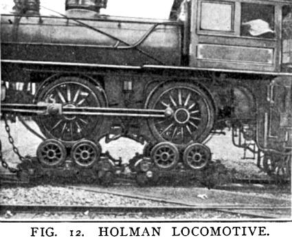 Holman's
Absurdity. Holman's
Absurdity.
It might have been supposed that the Fontaine experiment would
have deterred others from trying such an expensive experiment
again; but when an amateur gets seized with the malady for designing
a locomotive of an entirely new pattern, he generally produces
something startling.
In 1887 The Holman Locomotive Company had built in Philadelphia
the locomotive illustrated in Fig. 12. It was immediately assailed
by practical railroad men and others for my opinion of this, the
latest monstrosity. I had not seen even a picture of the engine,
but descriptions were freely written. My opinion, expressed in
LOCOMOTIVE ENGINEERING, was: "It is a humbug. It is sound
engineering to hold that every piece added to a machine, after
it has reached the practical stage, is a source of weakness. A
triple set of wheels under a locomotive would be proposed only
by one who is densely ignorant of mechanics."
Next notice in the same paper reads: "There appears to
have been some method in the madness of the parties who got out
the absurd Holman locomotive.
"They are advertising in Philadelphia papers that a company
has been formed to sell this kind of locomotive, the capital stock
being $10,000,000. They offer to sell the stock for $25 a share,
the par value being $100. They make the claim that this sort of
engine is destined to be the locomotive of the future."
Next notice, also in the same paper, reads: "The parties
exploiting the Holman locomotive are advertising their stock in
numerous newspapers, and claiming that the invention is certain
to come rapidly into general use. The effect of that has been
that numerous letters have come to us asking our opinion of the
thing. We gave a general answer, the first paragraph of which
reads:
"When we first heard of the Holman locomotive we supposed
that it was the invention of some harmless crank who did not understand
the elementary principles of mechanics, but we now believe that
it has been, since its inception, an ostentatious machine designed
to allure unwary capitalists into an investment which will be
of the same real value as throwing gold coin over Niagara Falls."'
The engine was run a few trips on a straight railroad in New
Jersey, which was used merely as a stimulant to stock selling.
Unfortunately many people with limited savings were allured, into
investing their hard earned money in this swindle, and they might
as well have given it to a highway robber.
One painful case that was pushed to my attention will illustrate
the danger of taking stock in things recommended by friends. Mrs.
Marion French had sufficient money in United States bonds to produce
her an income of $570 a year. Some idiotic friend advised her
to invest in the Holman Locomotive Company's Stock, assuring her
that she would more than double her income without risk. Our washerwoman
never loses a chance to ask me when the Holman Locomotive Company
will begin paying dividends.
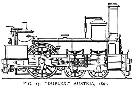 The Austrian
Duplex. The Austrian
Duplex.
There is no question that destructive blows are imparted to
the rail from the unbalanced weights of the driving wheels. Inventors
were early in the field to eliminate this blow by an opposing
force, and, incidentally, to make a smoother working engine. This
idea brought forth in Europe the Haswell locomotive, shown in
Fig. 13. That engine, which was built in 1861, at Vienna, for
the Austrian State Railway, excited much attention at the International
Exhibition of 1862, where it was exhibited. The engine had two
cylinders on each side, the power from the pistons being transmitted
to crank pins diametrically opposite to each other, the expectation
being that the momentum of each set of reciprocating parts would
balance the other set.
The "Duplex," as the engine was called, was very
powerful for that day, the cylinders being 10-and-seven-eighths
ins. in diameter, with stroke of 24-and-seven-eighths ins.
The driving wheels were 81 ins. in diameter. There were 15 sq.
ft. of grate area and the heating surface was 1,344 sq. ft. The
designer of this engine expected that it could be run with absolute
steadiness, at excessively high speed, and the reports made of
its performance in train service justified the belief concerning
steadiness, but the advantage gained was not considered of sufficient
importance to justify the repetition of the experiment.
The railway world had not begun talking about the so-called
"hammer blow" in 1862, but the unsteadiness of many
locomotives at high speed made itself manifest and various schemes
were resorted to for the purpose of remedying the defect which
was largely due to bad counterbalancing of the driving wheels.
The patent office records tell of many inventions being produced
for making locomotives run steadier at high speed, but nothing
of a permanent character has displaced counterbalance weights
placed in the driving wheels.
During the iron rail period considerable ingenuity was devoted
to inventions calculated to reduce the wear of rails, due to impact
of the wheels. It was supposed for years that a low center of
gravity saved the rails from destructive shocks. Years of experience
demonstrated that a low center of gravity tends to lead the wheels
into imparting destructive side shocks to the rails, but that
was an article of knowledge that came to the railway engineering
fraternity by very slow degrees.
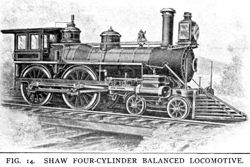 The Shaw
Four-Cylinder Balanced Engine. The Shaw
Four-Cylinder Balanced Engine.
In 1881 there was built at the Hinkley Locomotive Works, Boston,
a four-cylinder balanced engine, called the H. F. Shaw, Fig. 14,
which was industriously exploited as being entirely free from
the pounding and oscillating action of two cylinder locomotives.
The locomotive was substantially the same as Haswell's Duplex,
except that the cylinders were arranged side by side, transmitting
the power to crank pins diametrically opposite each other. One
of the crank pins connected outside the driving wheel at the same
position an ordinary crank pin would be located, and carried a
double crank, the middle of which was supported in a bearing secured
in an outside frame. That bearing was the driving fulcrum, a main
rod working at each side of it.
The engine was equivalent to one with two cylinders 16 x 24
ins., and driving wheels 63 ins. in diameter. The weight in working
order was 74,000 lbs., of which 25,600 lbs. was on the truck wheels.
The boiler had 14.8 sq. ft. of grate area, and 981.75 sq. ft.
of heating surface. The engine was well designed and built in
first class manner. It was used to a considerable extent on train
service in an experimental fashion, and worked quite satisfactorily.
The advantages claimed for the Shaw were: Perfect balancing,
an increase in the area of wearing surfaces, and, by dividing
the work between four cylinders, reduction of wear and tear was
accomplished, and, consequently, less risk of accident.
One claim read: "By utilizing all the force developed
upon the piston directly upon the driving wheels to rotate them,
the enormous loss through friction in ordinary locomotives is
entirely avoided." The soundness of that claim is open to
dispute and the other claims advanced are even more open to argument.
The Shaw did not languish unknown through want of advertising.
A gentleman named William E. Lockwood had the exploiting of the
invention at heart, and few railroad officials of any consequence
failed to learn how the "hammer blow" could be entirely
prevented.
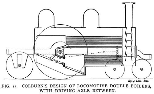
Some of the locomotives designed with special view to securing
low center of gravity are curious. Zerah Colburn was a sensible
railway man, with a good practical training as a mechanical engineer,
yet in 1854 he fell into the blunder of designing the absurdity
shown in Fig. 15. That engine had a double boiler, 43 ins. diameter,
arranged so that the driving axle was located between them. It
involved the use of two fire boxes, besides two sets of tubes.
The best that can be said about it is that it was a very courageous
design, but it came to nothing.
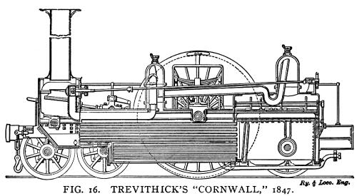
The attempt to make big boilers with low centers of gravity
is illustrated in Fig. 16, which shows Trevithick's "Cornwall"
built in 1847. It was a very awkward arrangement and required
a recess being made at the top of the boiler for the driving axle
to pass through. In service it was found that the engine did not
run any steadier than those with a much higher center of gravity
did. The very low center of gravity is a fallacy so far as steady
running is concerned, because when the wheel in its revolutions
receives sharp blows due to inequalities the shock is delivered
to the side of the rail. When the center of gravity is high, like
what it is in our Wootten engines, the blow strikes more on the
top of the rail than on the side.
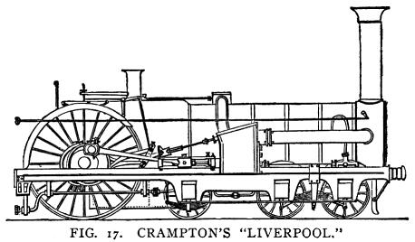
One of the principal oddities appears to be Crampton's "Liverpool,"
which was built in 1848, and is illustrated in Fig. 17. It has
a huge single pair of driving-wheels which was the Crampton peculiarity.
The designer's idea of putting the driving wheels under the foot
plate and the cylinders near the middle of the boiler was also
the idea of getting a low center of gravity, and a comparatively
big boiler. I had seen some experience with Crampton engines many
years ago, and never saw anybody who had a good word to say about
them, except those connected with the designing and building.
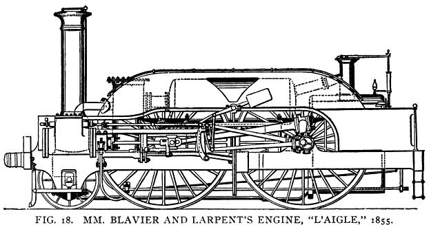
Fig. 18 shows interesting specimen illustrating the attempt
to introduce enormously large driving wheels in Blavier &
Larpent's engine "L'Aigle," built in France, in 1855.
The engine was exhibited in the Paris Exposition of that year,
and attracted a great deal of attention, but never did acceptable
work in service. It had cylinders 16½ by 22 in. stroke,
and driving wheels 2.85 metres, equivalent to 9 ft. 4 ins. diameter.
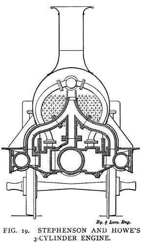
Another engine built and designed to obviate the disturbing
force due to the action of reciprocating is illustrated in Fig.
19 This engine was patented by Stephenson and Howe, in 1846. The
cross section looks like Webb's famous compound, but it was a
small engine, and was intended to prevent the nosing action so
well known with badly counter-balanced, outside connected engines.
The middle cylinder was 16-and-three-eighths by 18 ins., and the
outside, 10½ by 22 ins. The engine in service did not act
as the patentees expected it would, and the type was never repeated.
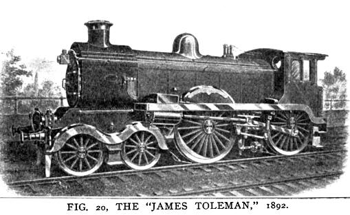
James Toleman's Four Cylinder Locomotive.
A most expensive sacrifice to good intentions was the "James
Toleman," Fig. 20, another four cylinder locomotive, but
decidedly different from the other two.
The James Toleman was exhibited in 1893, at the World's Fair,
in Chicago, and it evidently was expected to create something
of a sensation in this country. The engine represented the ideas
of an English engineer as to the best form of locomotive for handling
heavy fast passenger trains. It was designed by a Mr. Winby, of
London, and was built by Hawthorn, Lester & Co., Newcastle,
England.
That the engine was radically different from the ordinary locomotive
was apparent to the most casual observer; yet there were many
novelties about the machine that could be found only after laborious
examination. To obtain high speed and great power combined, two
pairs of driving wheels, 90 ins. diameter, were employed, and
each pair was driven by a pair of separate cylinders, the front
drivers being driven by inside cylinders located under the smoke
box, and the back drivers by outside cylinders set outside, back
of the leading truck. The inside cylinders were 17 x 22 ins.,
and the outside cylinders 12½ x 24 ins. A striking point
about the outside connections was the long piston rod necessary
to reach the guides. The most commendable part of this engine
was the arrangement that obviated the use of parallel rods. A
shifting link motion was used for the inside cylinders and Joy's
motion outside.
The boiler was one of the most curious features of this odd
locomotive. To obtain as much heating surface as possible while
maintaining a fairly low center of gravity, the boiler was made
elliptical, narrowed in the middle of the horizontal diameter,
so that it could be strengthened by cross braces.
A very serious objection occurred to me when I first examined
the engine, which was the complication of parts and the difficulty
that would be encountered in effecting repairs. I wrote:
"The designer appears to have had no consideration whatever
of the fact that repairs would have to be done frequently to a
locomotive pulling fast heavy trains. The engine is very handsome
and displays admirable workmanship. It has 1arge bearings and
strong connections; but we would not like to have the duty of
keeping a number of them in working order."
 After the
exhibition was over the James Toleman was p u t upon the Chicago,
Milwaukee & St. Paul Railroad, to haul ten parlor cars, 82
miles in two hours. It failed very decidedly on that service,
both from lack of steam and through breakage of parts. After the
exhibition was over the James Toleman was p u t upon the Chicago,
Milwaukee & St. Paul Railroad, to haul ten parlor cars, 82
miles in two hours. It failed very decidedly on that service,
both from lack of steam and through breakage of parts.
Fate of the James Toleman.
Replying to a letter of inquiry which I sent, Mr. A. E. Manchester,
superintendent of motive power of the Chicago, Milwaukee &
St. Paul Railway, wrote:
"The engine 'James Toleman' was some seven years ago turned
over to the Purdue University, La Fayette, Ind., as a museum feature,
and I believe is still there.
"As to the performance of the engine on our road will
say that we never got any practical results from it at all.
"In the first place the grate surface-and the size of
the fire box were not equal to the demands on the boiler, and
no adjustment of the front end or exhaust appliances was equal
to Staking care of the demands on the boilers.
"You will remember that one of the features of this engine
was that the flue sheet extended into the fire box. In other words,
it was a combustion chamber reversed, and it was found in practice
that all of the grate surface under this projecting portion of
the cylinder part of the boiler would not burn the coal, consequently
the grate surface was cut down to the limited amount that was
between the end of the flue sheet and the back end of the fire
box.
"The engine, as you no doubt remember, had four cylinders.
The inside cylinders connected with a crank shaft to the front
driving axle and was operated by a shifting link motion. The back
cylinders were connected by a wrist pin to the back driving wheels
and axles and were operated by a Joy valve motion. All of the
cylinders drew their steam from one niggerhead and dry pipe, and
the result of this was that whichever pair of cylinders, either
inside or outside, took steam first, there was not enough went
into the other cylinders to blow into the cylinder cocks, and
it was only with a light throttle and moving slowly that all cylinders
could be made to take steam at once. When but two of the cylinders
were getting all the steam, the tractive power on that pair of
wheels was not enough to take care of the work that the cylinders
would develop, consequently the engine would stand and one pair
of wheels would spin like a circular saw and the others would
be doing nothing.
"Mr. Winby, who was the designer and owner of the engine,
stayed with it, and had his mechanical engineer and a special
engineer whom he brought from England with him for something like
two months, until he became thoroughly disgusted and went off
and left it. We have not had a word from him for a number of years.
I think he has forgotten that he ever designed or owned the 'James
Toleman."'
French Favor Novelties.
France has given to the world a fair share of the freaks designed
to send the ordinary forms of locomotives prematurely to the scrapheap,
and, incidentally, to demonstrate what amateur designers could
do in wandering away from well trodden paths of engineering rectitude.
Gallic sentiment leans kindly to things that look new.
"The earth was made so various that the mind
Of desultory man, studious of change,
And pleased with novelty might be indulged."
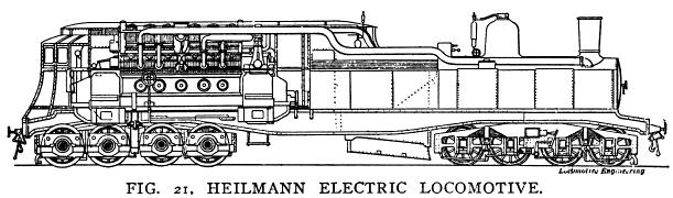
Heilmann Electric Locomotive.
The Western Railway of France experimented persistently in
1897 with electric locomotives, Fig. 21, which generated the electricity
in driving it. This form of engine was invented by J. J. Heilmann,
a Swiss engineer, residing in Paris. The first locomotive of that
type tried was considered to work so satisfactory that two others,
much more powerful than the first one, were made, one of them
being the subject of illustration which was copied from the Railway
World, of London. The body of the engine consisted of heavy steel
girders which was carried by two eight wheel trucks. Above the
rear part on the deck built upon the frames were placed the boiler
and coal bunkers, while the principal steam engine, the two generation
electric dynamos, the exciter with a special engine and the airbrake
apparatus were carried above the leading truck.
The boiler was of the locomotive Belpaire type, and provided
1,996.5 sq. ft. of heating surface. The grate area was 35.95 sq.
ft. The boiler pressure carried was about 200 lbs. to the sq.
in.
The engine was compound with six cranks set in a form that
was reported to give perfect equilibrium. The engine drove two
electric generators continuous current machines, independently
excited. The current supplied by the generators was said to develop
125 horse power at 62 miles an hour. It was calculated that this
locomotive would haul a train weighing 250 tons at the speed of
62 miles an hour, which seemed to me a small performance for the
expense involved.
The Heilmann locomotive formed a spectacle to the people of
Paris for only a few short months.
Thuile Locomotive.
Another expensive French novelty was the Thuile high-speed
locomotive, exhibited at Paris in 1900 by Schneider & Co.,
of Crensot, France, and shown in Fig. 22. That engine was designed
to haul trains from 180 to 200 tons, equal to about four Pullman
cars, at 75 miles an hour on level roads, and was calculated to
develop about 1,800 horse power.
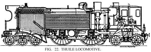
There were four coupled wheels, a full truck at the front and
a six-wheel truck under the back end, although the necessity for
this was not apparent, as there were only 59,000 lbs. on this
truck. This makes less than 10,000 lbs. on a wheel for this truck,
and under 15,000 for a four-wheel truck, which would seem preferable
to the extra pair of wheels.
The driving wheels carried only 65,000 lbs., or about 16,000
on a wheel—but little more than was carried by the trailing
truck. The total weight of the engine in working order was about
165,000 lbs., and the tractive power 15,652 lbs.
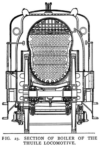 The boiler
was of a flattened section, as shown in Fig. 23, similar to the
"James Toleman" boiler, to get it between the wheels,
which were 8 ft. 2½ ins. diameter, and the method of cross-staying
is shown in the sectional cut. The diameter of upper portion was
about 54 ins., while the lower is 48.5 ins. The height was 79
ins. There were 183 ribbed tubes, 2¼ ins. in diameter and
14 ft. 3 ins. long, giving a heating surface of 2,941 sq. ft.,
which with 263 ft. in firebox gave a total of 3,204 sq. ft. The
boiler pressure was 213 lbs. The grate area was very large for
European practice, being a trifle over 50 sq. ft. The boiler
was of a flattened section, as shown in Fig. 23, similar to the
"James Toleman" boiler, to get it between the wheels,
which were 8 ft. 2½ ins. diameter, and the method of cross-staying
is shown in the sectional cut. The diameter of upper portion was
about 54 ins., while the lower is 48.5 ins. The height was 79
ins. There were 183 ribbed tubes, 2¼ ins. in diameter and
14 ft. 3 ins. long, giving a heating surface of 2,941 sq. ft.,
which with 263 ft. in firebox gave a total of 3,204 sq. ft. The
boiler pressure was 213 lbs. The grate area was very large for
European practice, being a trifle over 50 sq. ft.
Cylinders were 20 x 27½ ins., and a Walschaerts valve
gear was used. The total wheel base was 40 ft. 2 ins., and entire
length of engine, 46 ft. The cab, which had a windsplitting attachment,
was in front of the engine, while the fireman was at the rear—46
ft. away.
The tender was also of peculiar design, having ten 42-in. wheels
under it. The wheel base was 25 ft. 7 ins., and the tender weighed
about 49,000 lbs., empty, and 121,000 in working order. It carried
about 6,000 gallons of water and 7 tons of coal. I was indebted
to Engineering, of London, for the data given.
I examined that locomotive very carefully at the Paris Exposition
and discussed its peculiarities with some of the most eminent
engineers who were visitors at the show. The following conclude
notes which I wrote to my paper about the Thuile locomotive:
"The engine shows traces of very careful designing and the
construction work has been wonderfully well done. I listened to
several well-known European engineers discussing the merits and
shortcomings of the machine, and I certainly was surprised to
find that the consensus of that opinion was favorable. The writer
dislikes to be in the minority, but he has enjoyed many opportunities
of passing judgment on so-called original types of locomotives
that were going to push the common types out of service. He never
made a mistake of judgment in telling that the ordinary original
type of locomotive was a fake. He has now no hesitation in saying
that the Thuile will fall into rank with the Fontaine, the Raub
Central Power, the James Toleman and the Holman locomotives, which
are all of amusing memory."
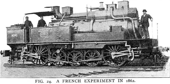
An Early Double Ender.
The oddity shown in Fig. 24 was one of several locomotives
built in 1862 by the Northern Railway of France. The best that
can be said of this locomotive was a remark made on a ridiculous
freak designed in the office of Locomotive Engineering, and
called the Gilderfluke, as a take-off on idiotic designs of locomotives
getting forced into notice. This engineer remarked, "the
thing would move." As may be noted, this was one of the early
double end locomotives.
La Parisienne.
A remarkable freak that was to be seen in Paris in 1900 bore
the above name. It had three pairs of driving wheels, 7 ft. diameter,
coupled, and two pairs of wheels of the same size carried the
tender. Its curious appearance was the only thing that made the
Parisienne worthy of passing notice.
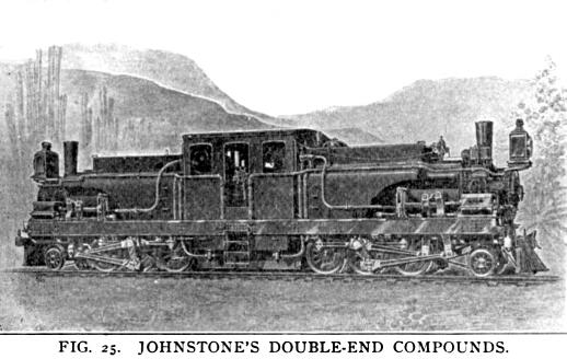 Johnstone's
Double-Ended Compound. Johnstone's
Double-Ended Compound.
A famous engineer once remarked to an inventor, who had presented
an extraordinary complicated arrangement of mechanism as an improved
valve motion, "You are suffering from abnormal inventive
fertility." An engineer gifted with the inventive faculty
is in danger of pushing his inventive fertility to a rank crop
that is expensive to harvest. I have always thought it was some
such inventing force that pushed F. W. Johnstone, mechanical superintendent
of the Mexican Central Railway, to design the locomotive shown
in Fig. 25, which was one of three built in 1892.
The engine, as will be readily understood, was a most extraordinary
form of a locomotive. It looks like two Mogul—2-6-0—locomotives
fastened cab to cab; but it is structurally a good deal more than
that. The reputed purpose of this odd type of engine was to provide
an extraordinarily powerful flexible motor for climbing the steep
mountain grades of the Mexican Central Railway, the flexibility
being sufficient to go round very sharp curves with the least
possible frictional resistance. The flexibility was obtained by
securing the driving wheels in a truck, which was free to move
in a line different from that followed by the main frames. In
the Mason bogie engines, the driving wheels were grouped in a
flexible truck which carried the cylinders. In the Johnstone engine,
the cylinders and boiler were carried on the main frames, separate
from the driving wheel truck.
As the cylinders were not in line with the driving wheels in
passing curves, it was necessary that a special method of transmitting
the power from the cylinders should be employed. This was done
in a very ingenious way through levers that transmitted the power
and at the same time compensated for the varying distances between
pistons and crank, due to the swivelling of the driving wheels.
Without the compensating arrangement it would have been necessary
to give the engine so much cylinder clearance that the loss of
steam would have been very great. The power transmitting levers
are seen in the back of the cylinders, connected at the top by
a short link and the bottom ends pinned to the front end of the
main rods. There were two of the latter, one connecting with a
crank pin, the other with a return crank. The piston transmitted
motion to the back one of the two levers, and that gave motion
to the front lever, which was fulcrumed securely to the frame
near its center.
The engines were compound, with annular cylinders, the high
pressure cylinder being in the center and the low pressure cylinder
forming the outside concentric ring. The high pressure cylinder
was 13 ins. diameter, and the low pressure 28 ins. The stroke
was 24 ins. It was calculated that each pair of cylinders would
develop power equal to a 19 x 24 in. simple engine.
That cylinder arrangement violated the principles relating
to the conservation of heat, for the comparatively cold, low pressure
steam encircling the high pressure cylinder would be certain to
exert condensing effects upon the steam in the high pressure cylinder.
Even in the hands of their friends it was difficult to keep the
engines at work, and after a few years of unsatisfactory service
they were changed to accepted forms.
An Original Form of Contractor's Locomotive.
Among the minor sacrifices to good intentions that were called
locomotives w a s that shown in Fig. 26. This was the first product
of the Pittsburgh Locomotive Works, and was built by Thatcher
Perkins, engineer and superintendent of the company, for the contractor
of a narrow gauge coal road near Pittsburgh named Bausman. The
workmen called it "Bausman's Rhinoceros."
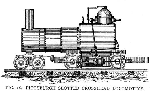
The curious thing about the engine was that it had no main
or side rods, the piston rods extending out on both ends of the
cylinders and connected to slotted cross heads, fitted with sliding
blocks, in which the crank pins worked. The valve gear was of
the Carmichael type, illustrated in the chapter on Valve Motion.
The Oldest Curiousity.
During the Diamond jubilee of the late Queen Victoria, when
all London was decorated with flags, streamers and emblems, the
headquarters of one of the well known cricket clubs in that city
had among their decorations the words, "Well played; 60,
not out." The old engine which we illustrate in Fig. 27 is
still at work, and the North .Eastern Railway of England might
well say of it, as the cricketers did of the Queen, "Well
played; 84, not out."
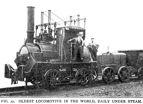 We are indebted
to Mr. Wilson Worsdell, chief mechanical engineer of the North
Eastern of England, for the photograph, diagrams and information
concerning this remarkable engine. Mr. Worsdell is of the opinion
that it is the oldest locomotive in the world that is daily under
steam, for it was built in 1822 and is now regularly used as part
of the motive power equipment in the collieries of Sir Lindsay
Wood, who is one of the directors of the North Eastern Railway.
The collieries are situated in the county of Durham, at a place
called Hetton-le-Hole, in England. We are indebted
to Mr. Wilson Worsdell, chief mechanical engineer of the North
Eastern of England, for the photograph, diagrams and information
concerning this remarkable engine. Mr. Worsdell is of the opinion
that it is the oldest locomotive in the world that is daily under
steam, for it was built in 1822 and is now regularly used as part
of the motive power equipment in the collieries of Sir Lindsay
Wood, who is one of the directors of the North Eastern Railway.
The collieries are situated in the county of Durham, at a place
called Hetton-le-Hole, in England.
The engine has vertical cylinders 10¼ inches in diameter
and 24 inch stroke, with cross arms instead of cross heads working
in upright guides which are braced diagonally from the top of
one to the bottom of the other. The cylinders rest directly on
the shell of the boiler, which is not covered with any lagging.
There is a small cab on one side, in which the "driver"
is evidently allowed to sit down. The halftone illustration shows
him with his hand on the brake apparatus. This is a form used
a good deal in the British Isles, and is an upright shaft placed
in a hollow stand. The shaft has a screw thread cut on the lower
end, upon which a nut works. The nut has two trunnions on either
side, which take the place of a pin in a lever. The nut can be
run up or down the shaft, according to the way the handle is turned,
and the nut, although moving the end of a lever, always remains
parallel to itself.
The familiar "life guards" are to be seen in front
of the leading wheels. These are the vertical metal bars which
reach from the buffer beam to very nearly the rail level. They
are used throughout the British Isles and on the continent at
the present day. The sand box is seen comfortably nestling against
the side of the smoke box on the running board level.
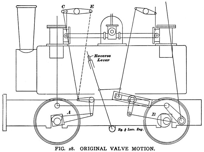
The line engraving, Fig. 28, shows the valve gear at A
as it was originally built. The motion which actuated the valve
was obtained from a cam working in a square box. This motion was
conveyed through connecting links and rods to a lever fixed above
the steam chest. The valve worked in a box on the side of the
cylinder. The reverse motion was obtained by the driver withdrawing
bolt C and moving the rod to the other end of lever and
replacing the bolt at point marked E. This had to be done
separately for each of the cylinders. About the year 1880 the
old arrangement was altered. An eccentric sheave was fixed on
the axle instead of the cam, and the motion was conveyed through
a link, as shown at B. This arrangement is more clearly
shown in Fig. 29. The reversing lever was so fixed so as to shift
the link block in the link. The halftone illustration exhibits
this arrangement also, but the adjacent ends of the links and
the bottom of the reverse lever and its fulcrum are hidden behind
a metal plate.
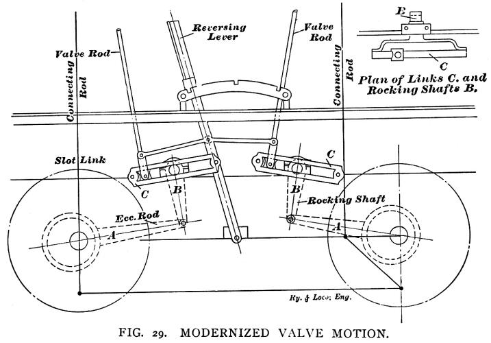
According to our modern rule, the engine has a calculated tractive
effort of about 4,700 pounds.
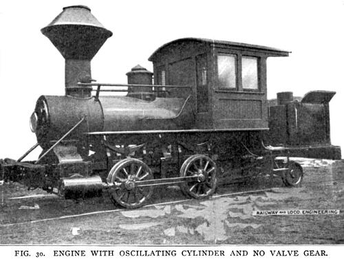 Oscillating
Cylinder Locomotives. Oscillating
Cylinder Locomotives.
Oscillating cylinders were in great repute, for steam engines
for a few years, especially for marine power, and claims were
persistently made that an oscillating engine would transmit more
power to the crank pin than any other. Those favoring that kind
of engine held that it had no dead center to speak of and that
the leverage was correspondingly great.
A locomotive might not be regarded as a good subject for the
application of oscillating cylinders, yet that has been done successfully
and Dewey Bros., Goldsboro, N. C., are making such locomotives
for logging railroads, one of them being shown in Fig. 30. As
will be observed, the piston rods are coupled direct to the crank
pin. The engine is reversed by means of a four-way cock which
changes the steam pipe into an exhaust pipe and vice versa. The
cylinders oscillate on a trunnion which passes through the middle
casting. This trunnion passes through a coil spring which pulls
the cylinder up against the saddle, allowing it to oscillate and
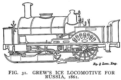
yet make a tight joint. No valve gear is necessary. Fig. 31 is
a line engraving of Grew's Ice Locomotive for Russia built in
1861.
Oddities
| Contents Page
|


