|
 The Weems Electric Railway. The Weems Electric Railway.
Engineering News—September 14,
1889
This company, whose tests on their Baltimore track, we noted
in our issue of Aug. 31, and which proposes to construct a second
and longer 5-mile track at Garden City, was organized Feb. 13,
1888. The experimental track is at Laurel Station, on the Washington
branch, Baltimore & Ohio R. R., about midway between Baltimore
and Washington. It is precisely a 2-mile circle constructed with
only 16lb. rails, and with rather rough surface and broken grades.
The track is of 24-in. gauge. The motor is 18 ft. long by, say,
2½ x 2½ ft. cross-section, or 6.25 sq. ft., pointed
in front. Two cars follow it, closely telescoped together, the
rear car of the train being also pointed to diminish suction,
so that the train is practically one snake-like body, pointed
at head and front. The experimental train complete weighs about
6,000 lbs.; and this train, there appears to be no room for doubt,
has been repeatedly driven around the 2-mile circle in somewhat
less than a minute, affording some basis for the hope and belief
expressed, that with better track and more complete appliances,
speeds of 150 miles per hour may be attained. The projectors even
talk of running "mail trains" at the rate of 4 or 5
miles per minute, or at the rate of only 228 to 182 minutes (3
to 3.8 hours), between Chicago and New York.
To see how reasonable such expectation is, we may start from
the reported fact that they have actually made 2 miles per minute
on their experimental track. The dynamo used is of 60 H. P., and
was pushed to its full capacity. Then
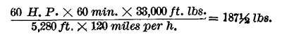
which is the average frictional resistance of the train under
these stated conditions. This amounts to 62½ lbs. per ton
of total resistance; or, if we consider a third of the resistance
only to have been true frictional resistance, or 21 lbs. per ton,
we have left 125 lbs, as the air resistance, which amounts to
precisely 20 lbs. per ton per sq. ft. of sectional area. By Smeaton's
scale, the best we have, this would correspond to the pressure
from a wind of some 62 miles per hour only; but Smeaton's scale
not being wholly reliable, and the apparatus being pointed at
each end to reduce air resistance, this corresponds sufficiently
well with the alleged facts for the latter not to seem incredible.
We were somewhat surprised at these results, not expecting
them to correspond so closely with what theory would indicate,
but they evidently do that fairly well. At present the principal
practical use contemplated is the handling of mail and express
matter, to which accidents due to the very high speed will be
of minor moment. It is also expected, however, to extend the principle
to passenger transport, after its use for freight has been made
successful. A rail with a wide exterior flange is used, tinder
which a catch rides so as to prevent derailment.
The adhesion is increased several fold by the electric current,
otherwise there would not be enough for such rapid motion. The
train is entirely controlled from the dynamo station, and there
are no runners on board of it. Stopping is effected as follows:
There are brakes actuated by powerful springs which normally press
against the wheels. When the current is turned on, it acts through
a coil on an armature attached to a toggle joint arrangement,
in the usual manner, so that the brakes are held off so long as
the current continues. Should there be any interruption in the
track or conductor, as for instance, an open drawbridge, the current
instantly stops and the brakes go on. The current can if desired
be reversed, and the train then run backwards, so that it can
be brought back from any moment to the starting point.
Using large copper conductors, it is expected that a single
dynamo station can operate 40 to 50 miles each way, so that but
one would be essential between Philadelphia and New York for example.
It is not proposed to have more than one train on the same "block"
at once. An automatic register is used, showing the position of
the train. The center of gravity of the train is below the axles.
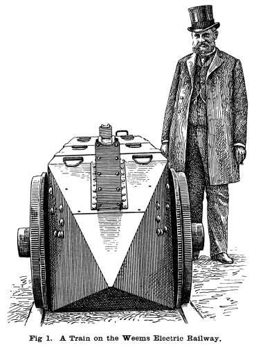
We give herewith illustrations of the motor and train from
photographs taken at the company's experimental track at Laurel.
Fig. 1 shows an end view of the train on the siding with the company's
shops in the background. The pointed nose of the motor is about
the only feature of interest which this view shows. We must confess
to a most thorough inexperience in the design of the prows of
locomotives intended to cleave the air at the rate of two or three
hundred miles per hour; but, it certainly seems that an alteration
in the design of the "beak" of this machine would make
a large difference in air resistance. As now designed, it seem,
as if the air sliding past the side planes would be held by the
front wheels. It would seem better to have the sides straight,
and let the machine cleave the air with a horizontal edge instead
of a point. Wheel covers, which the air could pass smoothly over,
would also tend to diminish the air friction.
This illustration also gives a very fair picture of Mr. DAVID G. WEEMS, the inventor
of this new system of transit and the general manager of the company
which is now perfecting it for practical use.
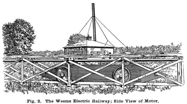 Fig. 2 is
a side view of the motor, and shows also the manner in which the
track is fenced, a very necessary precaution. It would probably
be found advisable to add also a few strands of barbed wire to
save the lives of dogs, pigs, lambs, and such small game, as well
as those of the intoxicated gentlemen whose penchant for the railway
track as a sleeping place is well known. Fig. 2 is
a side view of the motor, and shows also the manner in which the
track is fenced, a very necessary precaution. It would probably
be found advisable to add also a few strands of barbed wire to
save the lives of dogs, pigs, lambs, and such small game, as well
as those of the intoxicated gentlemen whose penchant for the railway
track as a sleeping place is well known.
It would also be necessary to enclose sections entirely wherever
snow was likely to drift upon the line, since a train of this
weight, bolting along at a few hundred miles an hour, would be
likely to be transformed into a rocket if it struck a fair-sized
snow drift.
We have not deemed it necessary at this stage in the development
of this new transit scheme to present any detailed illustration
of the mechanism of the motor end cars. The general form of the
motor is shown in our engravings. The dynamo which drives it receives
the current from an overhead conductor.
Oddities
| Contents Page
|


