The Otis Elevating Railway
Scientific American—October 5,
1895
The eastern end of the Catskill range has been a favorite mountain
resort for many years. Until within a short time the hotels on
the top of the mountain were accessible only by a tedious stage
ride up the face of the mountain, or by the rather circuitous
route of the Stony Clove Railway, running from Phoenicia, on the
Ulster and Delaware Railway, to the top of the mountain.
Recently an inclined railway has been built up the side of
the mountain lying toward the valley of the Hudson, and extending
front Otis station, on the Catskill Mountain Railway, nearly to
the top of the mountain. This railway is known as the Otis Elevating
Railway, having received its name from the firm of Otis Brothers,
the well known manufacturers of elevator machinery.
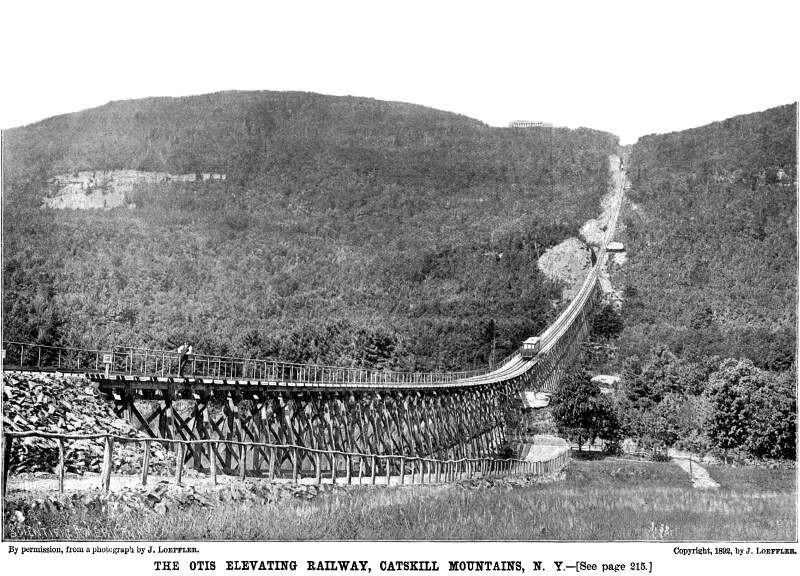
The road is 7,200 feet long, with a rise of 1,600 feet. It
runs in a straight course down the mountain without any lateral
deviation, but it is not a true inclined plane. It is made up
of four curves, two of which are circular while two are parabolic.
This plan has been worked out by the engineer, Thomas E. Brown,
to secure, as far as possible, the balance of the two cables used
in moving the cars, the cables alone weighing ten tons each.
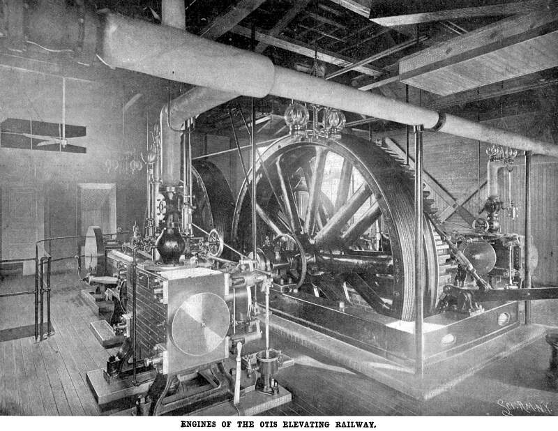
The engines which operate the cables are located at the upper
terminus of the railway, within about three hundred feet of the
old Catskill Mountain House, which is seen in the general view.
The engines are of the Corliss type, built by the Hamilton Corliss
Engine Works. They are seventy-five horse power each at one-fourth
cut-off, the diameter of the cylinders being twelve inches, the
length of the stroke being thirty inches. The shaft, which is
common to both engines, is provided with two brake wheels, which
are each encircled by a brake strap. The shaft also carries a
pinion which engages a spur wheel on the shaft of one of the cable
drums. The driving cable drum has a loose rim provided with a
grooved periphery which receives the cables, the rim being carried
by friction. The other cable drum simply supports the cables.
The cables, which are connected up parallel, are attached to one
car, and passing twice around the drums extend out of the engine
house around a sheave, thence to the other car.
The track, as will be seen by reference to the general view,
has three rails, the center one being common to both cars, there
being a separate outer rail for each car, except at the turn-out,
shown in the general view, about half-way up the mountain. Here
for a very short distance the tracks separate into separate and
distinct two-rail tracks. With this arrangement, it will be seen
that when one car goes up the other must necessarily go down,
and, so far as the cars themselves are concerned, they balance
each other.
The cars have a seating capacity of ninety passengers, a caboose
being provided for a proportionate amount of baggage. The seats
are like those used in the elevators of the Eiffel tower, being
constructed on a curve which enables the passengers to easily
adjust themselves to the different inclinations of the railway.
To the ties on each side of the central rail are secured heavy
timbers which extend from one end of the railway to the other,
and upon each car is firmly attached a clutch capable of gripping
this timber upon the top and sides. The clutch is under the control
of a governor which rolls on the top of the timber. Any considerable
increase in the speed of the governor releases the clutch 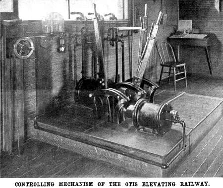 and causes it to be thrown forcibly into the
timber, thus instantly arresting the downward motion of the car.
The two cables are also attached to a swivel plate upon each car,
which is connected with the clutch mechanism, so that should one
of the cables fail, the other will turn the swivel plate and cause
the clutch to engage the timber. The clutch can also be operated
by hand at the will of the conductor. and causes it to be thrown forcibly into the
timber, thus instantly arresting the downward motion of the car.
The two cables are also attached to a swivel plate upon each car,
which is connected with the clutch mechanism, so that should one
of the cables fail, the other will turn the swivel plate and cause
the clutch to engage the timber. The clutch can also be operated
by hand at the will of the conductor.
Upon the cable-driving drum is placed a strap brake which,
together with the brakes on the engine shaft, is operated by air
pressure. The engines are provided with link motion, and the shifting
of the engine may be effected by means of an air cylinder in the
tower above the engine room. In fact, all the controlling mechanism
may be operated by simply turning air valves connected with the
air brake system, and to insure the stopping of the cars at the
ends of the road a lever is provided, which is moved by the car
so as to throw into action the engine-controlling levers and brakes,
to immediately stop the engine and to hold the cable securely
in the position in which it is stopped.
In the tower in front of the controller is a governor driven
by the engines below, which indicates the maximum speed by closing
an electric circuit and ringing a bell. A wire extends from one
end of the road to the other for electric signaling, and telephone
system has been provided, by means of which telephonic communication
may be had between the cars and between the cars and the stations
at the ends of the road. The passengers as they are carried up
this road survey a magnificent scene which can never be adequately
produced on canvas. For the details here presented we are indebted
to C. F. Parker, assistant engineer.
Stories Page | Contents Page
|


