The Design and Construction of Railway
Shops.*
Engineering News—1889
*A paper by J. Davis BARNETT, Assistant Mechanical
Superintendent Grand Trunk Railway in the Transactions
of the Canadian Society of Civil Engineers.
The author wishes to record a few notes on the design and construction
of railway shops, and purposes, not only to treat of the peculiarities
that mark those of North America, but also to contrast some features
with European practice, and if possible to indicate what is and
what may be the modern development and progress in this art.
LOCATION.
A natural starting-point is the location of the shops with
reference to the terminal stations of the railway and to some
large town; also the choice of land and its amount. A statement
of the best American practice in this matter is given by Mr. C.
PAINE in the chapter on "Shops and Engine Houses" in
his "Elements of Railroading." A point he strongly emphasizes,
that more than enough land should at first be purchased, even
if afterwards it is sold as building lots, will receive a unanimous
endorsement.
FOUNDATIONS.
It would, for the present purpose, be a waste of time to enumerate
those matters common to all dry, solid, and effective foundations,
but it may be remarked that in northern climates, it is better
that the sides of foundation walls and piers be sloped rather
than stepped, so as to prevent as much as possible the earth gripping
the wall, as it expands under the action of frost.
When the main supports of the overhead weights—such as
roof-principals, crane-tracks, shafting, etc.,—are iron pillars;
and "made ground" covers to any depth the natural foundation
bed, the comparatively low price of iron has proved it to be economical
to build short foundation piers, and to allow the iron pillars
to run down below floor level, to the piers, instead of carrying
up the piers to floor level, the pillars being socketed into broad
cast-iron bases, bedded in cement.
Pillar footings and column bases, when above floor level, are
usually bedded on rolled sheet or melted pig lead. The author
is of the opinion that the running in, between base and cope stone,
of a fine cement grout, would be as neat and effective, and certainly
cheaper. Less concentrated weights, such as stationary engine
and pump beds, and the footings of heavy machine tools, are satisfactorily
bedded on their foundations with melted stick-sulphur.
Another instance of iron being used to reduce the first cost
of foundation may be seen in the new erecting shop of the Grand
Trunk Railway at Stratford, where, instead of making continuous
walls to carry the rails supporting the traverser table, it was
found less costly and quite as efficient to build disconnected
piers, and span them with wrought-iron beams of I section,
which carry the rails laid upon them longitudinally, and support
the flooring laid transversely.
WALLS.
It is advisable to emphasize the apparent wall construction:
a good shop looks substantial. This is best accomplished by using
bold pilasters or large piers to receive all roof and floor beams,
setting them so that they stand out prominently, and spanning
the panel between them with comparatively thin bonded walls, free
from bats, if of brick.
This method of straight lines and prominent offsets not only
satisfies the eye, but is of pronounced value in localizing and
absorbing the vibrations received from the roof or machinery,
and closer attention to these matters would result in our shops
having a less tame, a less ugly, appearance, and a longer safe
life. The permitted outlay on such new works rarely admits of
the wall surface being broken into ornamental lines, or varied
in color; but it is always possible to make a strong bony skeleton;
whose very angularity will instinctively satisfy, by appearing
to be quite equal to its special duty.
ENGINE HOUSES OR LOCOMOTIVE SHEDS.
Intended for little else than the temporary storage of locomotives,
engine houses in America vary more in first cost and permanence
of material used than in type of design. The ordinary arrangement
in plan is an annulus or segment of an annulus, whose center is
that of the unroofed turntable, giving access to the radial tracks,
each leading into a single locomotive stall. The economics, in
the construction of the annulus are: either a narrow span of trussed
ridge roof: or a so-called flat roof (angle of 5°), offering
little obstruction to wind, and permitting the use of an inexpensive
roof covering; low walls—the roof timbers are sometimes lower
than the top of the engine chimney—and a short length of
wall, as it is limited to the ends and outer ring, the inner ring
being formed by the wooden door and door posts. A flat roof supported
by pillars gives a very stiff building for the limited amount
of material used; and if sloped inwards, the roof drainage is
a simple matter.
The stack of the locomotive, naturally going to the higher
part of the building, brings its front end close to the outer
wall containing the windows, so that the most light is received
where it is needed— the moving part of the machine.
Extending back into sparsely settled districts, as do many
of the new railways on this continent, the primary consideration
in the erection of their buildings is low first cost, a future
development of traffic being relied upon to provide the revenue
for erecting permanent structures. Hence, segmental engine houses
of wood, with flat, gravel-covered roofs, are common; and if the
materials for the ash-pit, and its drainage, do not prove unusually
expensive, they can be built for $850 per stall, the foundation
consisting of cedar posts, 6 or 8 ft. apart, carrying a mud sill,
on which rests a pine frame of 6 to 8 ins. square scantlings,
the roof being single sheeted with 1 or 1¼ in. tongued
boards, and coated with paper felt, tar, and gravel; the ash-pit,
25 ft. long, being of brick or stone, and one iron smoke-jack
being provided. The shell of a similarly rooted building with
brick walls and stone foundation costs about $1,000 per stall.
It was common some years ago, in northern climates, to sheet
with inch boards on both sides of the scantling, and to fill in
between with sawdust. This hastened decay by holding water and
vermin, and the better practice now prevails of putting both sheetings
outside, with tarred felt or thick paper between them. The use
of clapboards or shingles for outside sheeting much improves the
otherwise primitive appearance of such an engine house.
The more permanent structures of this class are of brick, and
those of modern date have roof principals, rafters, and deck-ridge
beams of wrought iron throughout; the covering being of slate,
preferably of small size, 8 x 16 or 9 x 18, with a quick angle
or slope, at least equal to ¼ of span, which is never less
than 66 ft.
In Canada, slate is rarely used for shop-roof coverings. Mr.
J. W. HARKOM (Member) informs the author that he has used New
Rockland slate on an engine house in Maine five winters without
repair being needed, and he is familiar with roofs that have been
covered with it for ten years, that show no injury from frost.
Our native slates are very compact,—a point greatly in their
favor. A report of the State Geologist of Vermont shows that the
slate in this neighborhood has a water absorption (under vacuum
test) of but 1/400 of its weight. Mr. HARKOM also mentions a successful
experiment he carried out at Athabaska, with the object of getting
rid of the icicles that form at eaves, due to melting from heat
communicated through the roof slating. He double-boarded or sheeted
on the purlins, and then laid wood strips 1½ by 1 in. thick
on top, at proper distances apart, to which strips the slates
were nailed. The air space below secures fairly equal temperature
on both sides of the slate, thus preventing the excessive cave
icicles common to slate-covered engine houses.
The fire risk from a roof covering of shingles set in cement,
and—occasionally lime—washed, is very slight; in fact,
in high winds, with many live sparks flying about, it is probable
that shingles so treated are safer than slate.
A liberal surface of glass is provided in the outer ring wall.
Skylights flush with roof, being difficult to keep clean both
inside and out, are of little use; and the small portion of each
large door (forming the inner ring) that can be fitted with windows
makes it necessary to depend largely on the outer ring wall for
natural light.
As to the number of engine stalls required, any railway in
a moderate climate, having an engine house capacity equal to 60
per cent. of the locomotive stock, is well equipped; many American
railways being content with 50 per cent.
In Great Britain a very common form of engine house is the
longitudinal, with parallel through tracks, and exit at both ends.
Their capacity varies, rarely exceeding 80 engines. The roof is
usually of the saw-tooth pattern, a series of narrow spans, supported
by hollow iron pillars, forming conduits for the water from gutter
in roof valley to underground drains. The roof is hipped unequally,
favorite angles being 60° and 30°, and that side more
nearly vertical is glazed with three-eighth in. rolled or rough
plate, and if possible is arranged to face north, so as to give
a good light equally diffused throughout the wide building, without
too much inconvenience from the direct rays of the sun. Snow and
frost prevent the saw-tooth roof being used in Canada, (the author
not knowing of a single example on this continent north of the
State of New Jersey); hence our roofs are of single slope ("flat")
or single ridge of quick pitch; and as skylights have but a partial
efficiency, the necessity for securing light from the side walls
limits the width of a longitudinal engine house.
An excellent example of this type of house, built by the Grand
Trunk Ry., at Montreal, is 76 ft. wide by 282 ft. long, with five
parallel tracks through it, giving liberal accommodation for 25
long tender engines. Any increase in capacity could only be obtained
by lengthening the building and tracks, which increases, out of
all ratio, the difficulty of working the longitudinal type of
house. This difficulty is the trouble and extra movement of other
engines necessary to get a locomotive out and ready for service,
should one on the same track in front of it be undergoing for
a few hours such light repairs as the renewal of truck wheels,
that prevented it from being moved until the work is completed.
American criticism says that this is the main defect in the longitudinal
type of house. It does not, however, in daily practice prove to
be as awkward as it looks, if definite tracks are reserved for
such repairs and for such engines as have to keep "shedday"
while their boilers are being washed out, and if the housemen
(engine turners) learn what part of the house each engine should
go to, before attempting to put it under cover.
Exit at both ends of such a house cannot be obtained where
the yard room is limited. At Cardiff, on the Taff Vale Railway,
England, the Locomotive Superintendent, being compelled to have
one end of his new engine house blank, put in the middle of its
length a traverse pit and table, crossing its ten tracks and then
passing out, through a pocket on side wall, to a parallel siding
in the yard. This gives practically three exits; with exceptional
economy in space. (See Proc. Inst. C. E., August, 1884, p. 243.)
The Great Western Railway of England has, in many of its engine
houses, combined both the longitudinal and the radial systems
under one continuous hip and valley roof, and the Northeastern
Railway, England, had such a preference for the radial system
that five turntables were put under one roof, 280 ft. wide by
450 ft. long, giving stallage for 95 engines. This is an extreme
case and is probably unique, although in passing, it may be noted
that the late HOWARD FRY, in designing the extensive workshops
for the West Shore Railway at Frankfort, N. Y., laid them out
so that the smithy, boiler-shop, foundry, erecting and machine
shop stand radially to an open turntable. Having, however, unlimited
land at his disposal, the tracks from the outer ends of these
buildings are connected by easy curves to the yard sidings, so
that a failure of the turntable or the blocking of its pit will
not necessarily block up all entrance to these shops, such being
the case with the tracks in an engine house which converge on
a central turntable as their sole means of exit. The Burlington
& Missouri River Railway at Plattsmouth, Neb., also has most
of its shops in the shape of segments of an annulus centering
on one turntable.
The best radius of track curve is an unknown quantity, but
the New York Central Railway safely uses curves as sharp as 160
ft. radius for their city freight-house.
The author would strongly endorse the longitudinal type of
engine house. It is eminently serviceable where a large number
of engines have to be turned out almost together in the busy portions
of the day. An English officer, daily handling about 400 train
engines at one terminal, in comparing the two systems, said that
if turntables controlled the exit of his engine houses, he believed
it would be impossible for him to get the engines out on time
for their trains, even with additional space and men placed at
his disposal.
And this type as readily suits small establishments. An engine
house recently erected by the Grand Trunk Railway at Lindsay (under
the supervision of the author) is 250 by 62 ft. It has two through
tracks, with continuous ash-pits for 10 running engines, one through
track for engines under repair, being washed out or waiting under
steam between trains. Parallel with the window of one side wall
are two stationary boilers with overhead apparatus for sand storage
and drying, three smiths and other fires, a stationary engine,
a force pump with underground water supply tank, and still continuing
in line with the shop and main shafting are wheel lathes and other
iron-working machinery, the fitters' benches, and the wood-working
tools and benches, followed by foreman's office, clerk's office,
and a two-storied storeroom, with oil tanks below ground, the
whole resulting in a cheap, compact arrangement, every foot of
floor space being used, while every corner and detail is well
under the eye of the foreman. The tracks in yard form a triangle
(or Y, as it is called), and a turntable with its pit is
dispensed with, thus getting rid of one source of probable failure
and delay in getting engines out "on time."
Many engine houses are now equipped with a continuous pipe
1½ or 2 ins. diameter, having branches to each stall and
flexible couplings to each engine. Its uses are various. The steam
and water from a boiler to be "blown off" and washed
out are sometimes used to heat the water with which the washing
out is to be done. The pipe may be passed into a boiler of cold
water, so as to shorten the time in raising steam after a washed-out
boiler is refilled, and sometimes it is connected with the jet
blower at base of locomotive chimney, and the steam used in creating
a draft to quicken the newly lit fire. The two latter arrangements
prevail where an injector or inspirator is used to give the washout
water-pressure.
OIL HOUSE.
A special feature of American engine-houses—the outcome
of the extensive use of mineral oil for lubrication as well as
for light—is a detached oil house, a fireproof brick structure,
with iron roof; roof covering and shutters, and concrete or asphalt
floor. Underneath it (below track level) are iron storage reservoirs,
with inlet-pipes so arranged that oil received in bulk can gravitate
from the tank-car into any one of them, from whence it is lifted
by hand or steam pump into small tanks on upper floor, and is
drawn thence by tap for engine and train use.
The concrete floor is at level of car-floor, or about 4 ft.
2 in. above rail level, to facilitate small shipments to out-stations,
which in the more perfect equipments is by means of circular iron
tanks holding 60 galls. The cellarage around storage tank and
the house is warmed by steam pipe from outside, and the artificial
light is gas, or, as at Indianapolis, electric, no lamp or torch
being admitted.
SAND HOUSE.
The sand used to increase the adhesion of locomotive wheels
would at first sight seem to be too small an item to require specific
attention; but eight or ten tons is a daily issue at central stations.
At Columbus, O., the sand store, having a capacity of 1,000 tons,
is a neat wooden building with hinged shutters at top of walls,
set so as to permit the air to assist in sand-drying; and the
floor is of dry brick set on edge, with tile-drain below. When
required for use, the top layer of sand is shovelled into hoppers,
containing live steam pipes one inch diameter and spaced two and
a half inches apart; when dry it falls through bottom opening
onto a concrete floor.
The Grand Trunk Railway has recently, by hand power, belt and
bucket elevators, lifted the dry sand into overhead reservoirs,
from whence it is allowed, through hose and molasses gate, to
deliver directly into sand-box on top of locomotive boiler.
GENERAL REPAIRING OR ERECTING SHOP.
The amount of floor space to be devoted to the general repairs
of locomotives and tenders, and its proportional division among
the various buildings, is a wide question, on which little has
been written; and in attempting to find an average taken from
existing practice, difficulty is experienced, due to so many workshops
manufacturing supplies for outstations and for other departments,
even when not manufacturing new engines.
Simply for repair purposes, the author is of opinion that there
should be floor or stall room in the erecting (repair) shop for
10 or 11 per cent. of the total engine stock. It may be expected
that 4 or 5 per cent. will be in the paint shop going out, or
in yard waiting to come into erecting shop for general repairs,
and that 5 per cent. are having their boilers washed out, or undergoing
running repairs of so trivial a nature that they can be done in
the engine house. This leaves 80 per cent. of the motive power
effective and at work daily.
To illustrate, we will suppose the total number of engines
on a railway to be 100; the working engines make a daily average
of 133 miles or 4,000 per month, which multiplied by the 80 effective
engines gives 3,840,000 miles per annum, and the repairs done
in the erecting shop have to balance the wear and tear of this
mileage.
The first question is one of time: How long does it take to
repair an engine? An average common in American shops is—
Heavy repairs occupy 90 days, equivalent to a wear of 100,000
miles.
Medium repairs occupy 60 days, equivalent to a wear of 70,000
miles.
Light and specific repairs occupy 30 days, equivalent to a
wear of 30,000 miles.
General average is 60 days (2 months) to a wear of 67,000 miles.
Each engine on a general average, occupying a stall for two
months, gives the output of repaired engines for an erecting shop
containing ten stalls as 60, which multiplied by the average mileage
of 67,000 totals to 4,020,000, a sum just in excess of the mileage
during the same period by the 80 effective engines.
There is (or should be) some relationship in size between the
erecting and other shops of the locomotive department, and Table
1 gives from recent practice the comparative area of the other
shops in percentages of the erecting shop.
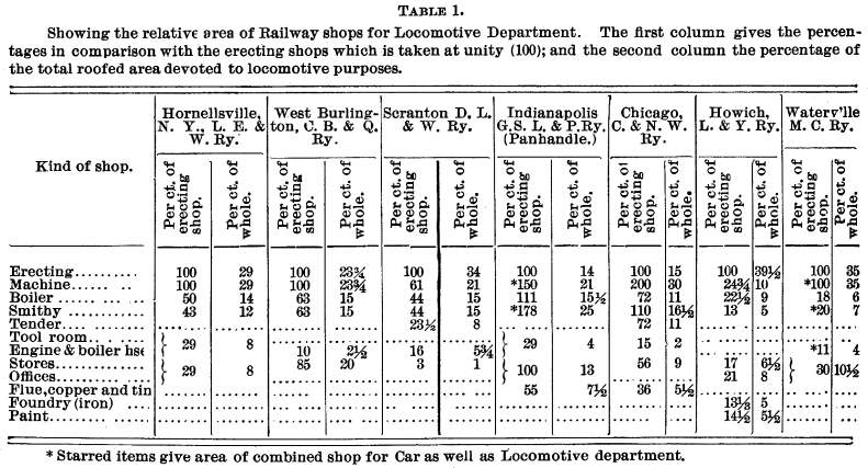
It will be seen that the proportions vary; and it must be so
when some establishments build more or less new work, while others
are restricted to repairs only; some are confined to locomotive
work, whereas in others material is manufactured for all departments,
including even the telegraph department.
Also the "size" relationship will be varied by the
uniformity and interchangeability of the parts of the engine stock.
Where their classes and styles are few, all the shops will be
comparatively small, and the delay to engines in the erecting
shop less. Thus, any such table will only permit of a mean average
being taken.
This being the case, under each heading is a second column,
in which the size of each shop is given as a percentage of the
whole, so that, given the total roofed surface that can be devoted
to the locomotive department, its proportionate divisions can
be approximately inferred.
In America, the ordinary arrangement for erecting shops is,
that the pits or stalls lie transversely to the main axis of the
building, admission to them being by a transfer table or traverser,
within the building in northern latitudes, and outside it where
snow is likely to cause but little inconvenience. There is an
obvious economy in size and cost of structure when the traverser
can be put outside; but its free movement cannot be insured during
a. Canadian winter, and an attempt to use one in Montreal was,
after much inconvenience, abandoned years ago. Hence, the shop
must be wide enough for its work, and for the length of the traverser
in addition, at once giving a span of roof justifying the use
of intermediate supports. Two rows of pillars are often used,
dividing the floor space into three bays, one on each side of
and parallel with the traverser pit, as this brings the work and
men close to the side windows. When the traverser is outside,
it is rarely that the floor is obstructed with more than one line
of pillars. Whatever be the number and disposition of these internal
supports, the roof is invariably of the single ridge or gable
pattern.
TRAVERSERS OR TRANSFER TABLES.
It was due to traversers being framed in timber that the pits
in which they moved were at first so deep, even exceeding 5 ft.
Rolled steel is now used for the frame, which is suspended front
the axle journals on both sides of eight small wheels, and for
which four parallel rails are provided. the full length of pit.
Much ingenuity has been used in the endeavor to reduce the inconvenience
of the pit, by making it as shallow as possible, and the Philadelphia
& Reading Railway, in its new car shops at Reading, has no
pit, only a flush asphalt floor from wall to wall. As, however,
the suspended or carrying rails of the traverser must be higher
than the fixed rail over which they move, it is arranged that
the tracks at each repair stall, instead of being spiked to cross-ties,
are carried upon longitudinal timbers about 10 ins. square, thus
lifting them above the floor level, and giving the necessary difference
in height between the traverser bed-rail and its suspended rail.
The author, not familiar with any example on this continent of
the European practice of making bed-rails for traverser and the
transverse or stall tracks flush with each other and continuous,
except where slightly cut at intersection to allow the wheel flanges
to pass. The shallow rails on the traverser only just clear the
bed track on the floor, and the vehicle to be transferred mounts
to them by running up tapered extensions of the suspended rail
that are hinged—or rather pivoted—on its ends, and which,
when not pressed down by the wheels of the on-coming vehicle,
are kept clear of the bed tracks by springs. This practice may
be said to be a development of the "Dunn Traverser,"
at one time in common use for the transfer of carriages at terminal
stations on English and Continental railways.
Having all rails flush, not only permits the rapid movement
of men and small material but allows the transfer, when traverser
is engaged, of vehicles from a stall on one side of bay to the
track immediately opposite. Having in view the possible failure
of the traverser, some shops are, and all should be, provided
with portable rails to span the width of pit.
Power to move the traverser is often communicated direct from
boiler and engine carried upon it. This, though convenient enough
perhaps for out door service, has proved to be an unmitigated
nuisance under cover in winter, when doors and windows must be
kept closed. Endless chains, the full length of the bed with stopping
and starting gear at one end, are sometimes used. The friction
is considerable, the chain having to be supported every 8 or 10
ft., and signals to control traverser movement have to be transmitted
over long distances.
Stout wire cable, traveling at same speed as chain, offers
less resistance, and if one of the forms of clip gear is used
on the traverser, the single attendant traveling with it has its
motion completely under control. The cable grip clip gear, used
at West Albany, New York Central Railway, is a simple form of
friction brake stopping the revolutions of a set of three geared
wheels. When locked, the traverser moves at same speed as rope.
Two sets of such wheels are used, so as to give both up and down
motion. When table is at rest, power is transferred to a capstan
used in hauling vehicles on and off the traverser. At Alton, Ill.,
Mr. W. WILSON causes a small, quickmoving rope to give motion
to one wheel and shaft, from which power to traverser and capstan
is communicated through bevel friction wheels. Speed of traverser
is slow, 25 ft. per minute, and that of the capstan is but 32
ft. per minute.
The outdoor traverser, built some years ago for the Wason Car
Shops, Springfield, is 50 ft. long, and weighs 11 tons, being
propelled by a boiler and engine of 12 H. P. A steam pressure
of 15 lbs. will move it without load; 30 lbs. with heaviest passenger
coach on; and 60 lbs. gives it a speed of 500 ft. per minute.
An interesting and successful attempt has just been made at
Aurora, on the Chicago, Burlington & Quincy Ry., to give motion
to a traverser and capstan through an overhead electric wire with
a small trolley running on it connected to a 7½ H. P. Sprague
motor. Its rapid motion is geared down, so that table can be run
either at 100 or 200 ft. per minute. The table is 65 ft. 9 ins.
long by 15 ft. wide, and weighs empty about 15 (short) tons. The
tractive resistance, unloaded, is about 250 lbs., equal to 17
lbs. per ton; loaded, it is 1,500 lbs. or 37 lbs. per ton. Experiments
on the Coln Minden Ry., at Deutzerfeld, give the resistance of
a traverser and load weighing 20 tons at 440 lbs., equal to a
tractive resistance of 22 lbs. per (long) ton.
Cotton ropes, moving at 3,360 ft. per minute, are used (under
cover) at Cologne on the Rhenish Ry. for coach traverser, friction
clutches being used to change the speed, so that the table has
a motion of 197 ft. and capstan of 64 ft. per minute.
Erecting shops, equipped with traversers at low level, need
in addition some means of lifting an engine off its wheels, and
a hoist is usually fixed in the roof timbers either close to entrance
or in centre of length of shop over the traverser bed. Lifting
power is variously communicated to hoist by belt from shop shafting,
by hydraulic pipe, by pneumatic pipe, and even by hand labor.
The European practice of making the erecting shop narrow compared
with its length, using three (or at most four) longitudinal tracks,
and spanning them for their whole length with overhead power traveling
cranes, has not often been adopted in America, although we have
specimens at the Canadian Pacific Ry., Montreal, Altoona, West
Burlington, Indianapolis, Roanoke, and at Hamilton, Ont.
Why so effective a method has been comparatively neglected,
it is not easy to say, as by its use there is an economy in floor
space, and the cranes can do duty for both traverser and hoist.
Undoubtedly the roof, or a portion of it, must be carried up higher,
so as to give head room for the cranes and their load to pass
over engines being repaired; but the interest on this outlay and
on that of the cranes (often exceeding the cost of both traveller
and hoist), is but a fraction of the money and time saved in the
daily working of the shop.
Two fish-bellied plate girders, extending from side wall to
side wall, with their ends supported on plate box trollies, usually
form the crane bed, and carry one—or better still, two—travelling
crabs. An independent boiler on crane, as a source of power, is
now rarely used; but from the shop shafting motion is communicated
to the crane by quick-moving ropes of steel wire, hemp, cotton
or rawhide. If the distance crane has to travel is short, say
under 150 ft., or if it is used in the foundry where heat and
dust would materially shorten the life of a fibre rope, then longitudinal
shafting (grooved or square), supported on tumbling bracket journals,
is often used. In almost all cases where the winch forms part
of the trolley, the transfer of motion to it from the end of crane
is by such a shaft, although in the original cranes of this class
designed by Mr. RAMSBOTTOM the high-speeded cord was carried along
the crane girder through the trolley to opposite end, and then
back to side wall, bending the cord often and shortening its life.
Messrs. Fowler of Leeds use steel wire rope similar to that
used in steam ploughing, their 12-ton crane being equipped with
a five-eighth in. diameter rope, moving at 270 ft. per minute.
One, of 40 tons capacity and 50 ft. span, has the rope speeded
to 400 ft. per minute, giving a slow lift of 2 ft. and a fast
one of 4 ft. per minute, with a cross traverse of 28 ft., and
a longitudinal motion of crane and load of 30 ft. per minute.
A 20-ton crane, using manila rope of full ¾ in. diameter,
running at a speed of 2,540 ft. per minute, has a slow lift of
3 ft., and a quick one of 51 ft. per minute, with a cross traverse
of trolley carriage of 16.8 ft., and a motion of the whole crane
of 47.5 ft. per minute. It has the hoisting winch at one end,
thus permitting the use of a 45-ft. span single box-girder, partially
open below, the trolley carriage travelling inside the box on
the angle-irons forming the lower web.
The seven original Ramsbottom cranes at Crewe used long-fibre
cotton rope five-eighth in. diam., weighing 1½ oz. to the
foot, having a tension of from 17 to 18 lbs. and a speed of 5,000
ft. per minute. Larger diameters, lower speeds, and cheaper material
are now used, as at Swinden, where 4½ in. rope at 970 ft.
per minute is employed. Messrs. Penn have used rawhide rope moving
at 1,500 ft. per minute; and a 50-ton crane employed on dock work
has had five years' service, without showing any wear on rawhide
rope of 1½ in. diameter.
At Aurora and Altoona, cotton rope with speeds of 5,000 ft.
per minute is used, giving, with the 25-ton cranes of the latter,
a slow lift of 15 ft. and a quick lift of 81 ft. per minute, a
crab traverse of 30 ft. and a crane travel of 50 ft. per minute.
The two cranes at Alton have each two crabs, so that the engine
is suspended and independently moved at the four corners, a decided
convenience when dropping frame and boiler on the wheels.
Where possible, it is an advantage to put the crane attendant's
platform below the main girder and close to the wall, so that
the work below, and not the crane machinery, is in his view.
Pneumatic floor cranes for light weights, although not common,
are used at Wilmington on the Philadelphia, Wilmington and Baltimore
Ry. and at the Paige Works, Cleveland. The Missouri Pacific Ry.
uses compressed air at from 60 to 80 lbs. pressure, to work small
three-cylinder Brotherhood engines for giving motion to boring,
valve facing, and other portable machines, the air being compressed
by a Westinghouse brake pump and distributed through small pipes.
In the engine house, or in the shop after ordinary working hours,
such portable motors can be coupled by rubber hose either to the
air pump or the boiler of the nearest locomotive in steam.
The pneumatic transmission of energy is not in itself economical;
but for the small powers mentioned, it is far cheaper than shafting
and more rapid than using manual labor.
At Seraing all classes of shop cranes are pneumatic. The reason
for this practice is that, with the large area under continuous
roof, the volume of pure cool air exhausted is of value in assisting
ventilation and increasing the general health of the workmen.
Our shops, sheds, and freight houses are rarely designed with
the object of reducing manual labor in lifting, and many of us
feel the regret expressed by Mr. Dory J. WHITTEMORE, ex-President
American Society of Civil Engineers: "I could not prevail
on our people to make use of cranes to the same extent that they
are used in England, and in this we are at fault." As an
afterthought, pillar and other fixed cranes are occasionally applied,
but their value and efficiency is limited, and for equal outlays,
by far the most economical results follow the use of movable cranes.
Hoisting by unskilled labor is one of the most expensive parts
of the old-fashioned plant which American shops yet retain. Recent
experience in the use of hydraulic drop-pits for removing single
pairs of wheels (although with all its advantages an inelastic
convenience) provokes such strong commendations and approval as
a labor and time-saving machine that it is probable that the period
is not far off when overhead power lifts will be common in our
shop equipment. The wear on the metal work of cranes is not rapid,
and an allowance of 5 per cent. per annum on first cost covers
all depreciation, except in the matter of lifting chains, which
require care and frequent testing. Wire rope has replaced lifting
chains with economical results, its only defect being an increased
diameter in pulleys and drums, the increase (about 25 per cent.)
not being excessive, as the speeds are slow.
To support an overhead travelling crane track, the plan usually
adopted is, to increase the thickness of the brick side-wall pilasters,
and arch over the window and door openings flush with pilasters
up to the elevated track level thus securing a solid, safe support
for crane travel, with the disadvantage of materially reducing
the width inside shop and the window openings. Rolled iron, bolted
to the walls, both for pillars and girders, would to-day be the
better practice. A good arrangement is to use stout cast-iron
pillars to support both the crane track and the roof principals,
filling in between them with walls of just sufficient thickness
to keep out the weather. It is difficult to use a single section
of wrought iron for this double purpose, as the support for the
track must be bolted on its side, and the weight from the crane
is not then brought directly over the foundation, resulting in
a tendency to throw the heel of the pillar outwards, and put the
roof principal into compression. By using cast iron pillars, and
varying their shape at the upper end, there is no difficulty in
bringing the crane weights vertically on the underground foundations.
The author is not familiar with any example of a cast-iron pillar
doing such double duty in any northern climate.
TRANSMISSION OF POWER.
In power transmission throughout workshops, small shafts, light
pulleys, and high-speed, flat leather belts are common in, and
belong properly to, America; but there is a growing tendency to
dispense with shafting in favor of rope, and to use hemp or manila
rather than wire rope. Examples of the use of wire rope are to
be seen at Altoona, St. Paul, and Proctor. The Buffalo, New York
& Philadelphia Railway has run its machine shop 312 ft. distant,
with ½-in. wire moving at a speed of 6,900 ft. per minute,
for two years without repair. At Columbus, motion is transmitted
by hemp rope moving at 1,500 ft. per minute, and Mr. DRUMMOND
at Cowlairs, Scotland, uses rope throughout, even for transmission
at right angles,—circumstances under which the Grand Trunk
Railway prefers the use of V leather belting. Satisfactory
instances of the use of hemp rope between engine and main shaft
may be seen in Montreal at the Grand Trunk Railway shops and at
the Redpath sugar refinery. A rope 2-in. diameter, moving at 3,000
ft. per minute will transmit 25 H. P., that is, a daily equivalent
to a 4-in. belt moving at the same speed. Three-ply manila rope
is better than four-ply. The pulleys should be at least 30 times
the diameter of the rope, and the shafts not less than 20 ft.
apart, the angle of the groove in pulley rim 40°, the rope
not being allowed to bottom in groove as in the case of wire rope.
Some actual tensions areas follows:
a manila rope 6½-in. in circumference, with a speed
of 2,972 ft., transmits 23 H. P. with a tension of 256 lbs.; another
at 3,782 ft. transmits 40 H. P. With a tension 349 lbs.; a third
has seven ropes of 1½-in. diameter, at 2,355 ft. transmits
34 H. P., with tension of 476 lbs., .the tendency with increasing
experience being to increase the tensions, which are still far
below those used with iron and steel wire ropes. Hemp apparently
suffers little from climatic influences; and its life, especially
at the weak point—the splice—may be lengthened by coating
it with beeswax and a little plumbago.
The Southern Railway of France has probably made the most complete
application of hemp rope in the minute division and transfer of
power. The through shaft in the shop is provided with numerous
V pulleys, by which motion is given to three-quarter inch
diameter hemp rope, so that at every point the power may be delivered
to light overhead cranes as well as to numerous specially designed
portable machine tools. For instance, in the boiler repair shop,
not only are the drills so worked at any angle or in any corner,
but the holes are tapped, and the screwed stays put in, much in
the same way as similar work is done to a limited extent with
the Stow flexible shaft.
Electric transmission has been used in Germany for some years
under restricted conditions. It has some advantages, as the conductor
is less clumsy than shafting, steam-pipe, or rope, its position
can easily be changed, and the motor is compact and less of a
nuisance than a small steam engine. Loss of power there certainly
is, but not much in the actual transmission between points far
apart, if wire of reasonable diameter is used, and the less the
power being taken off, the less is the percentage of loss in the
transmitter, the opposite rule holding good with shafting. The
chief loss is in the use of double machinery, the first to convert
motion into current, and the second to convert current into motion.
Every month is simplifying the problem and minimizing the waste;
and the ready adaptability of electro-magnetic machine tools (without
intermediate machinery) to the varied purpose of drilling, tapping,
rivetting, chipping, and caulking thick steel ship plates in position,
their high duty and rapidity of work, are shown in the paper by
Mr. F. J. ROWAN, recently discussed by the Institution of Mechanical
Engineers (Proc. Aug. 1887), in concluding which he expresses
his belief "that it will be found both economical and otherwise
convenient to adopt electrical distribution in engineering workshops,
instead of the existing system of shafting and belts, or even
hydraulic distribution of power."
Transmission of power by steam-pipe and independent engine
for each shop has not, up to date, been common in countries liable
to low temperature. In mild climates, the use of separate wall
engines with the cranks coupled direct to shop shafting is most
satisfactory, and a pair of locomotive cylinders are often used
for such service, as the engines occupy little if any floor space
when set vertically, and each shop can be run independently when
it is necessary to work overtime.
With the use of modern asbestos and silicate coverings, there
is but little loss by condensation in the long steampipe. Mr.
W. T. BIRD, in his careful experiments (see North of England Inst.
of Mining Engrs. Proc.1882-3) has shown that the condensation
in an exposed pipe 1,000 ft. long is sufficient to reduce the
steam to 76 per cent. of its boiler efficiency, while coating
the same pipe with silicate cotton raises the efficiency to 95
per cent.
MACHINE GROUPING.
At one time the aim in arranging a machine shop was to group
the large machines close together, so that the heavy and bulky
material steadily progressed from one to the other without retracing
its path. With the adoption of light overhead cranes and single
rail tramways for moving heavy weights, the rehandling of raw
material has lost much of its importance and most of its expense,
so that the favorite arrangement is to mass similar machines of
all sizes close together, permitting one skilled man to be put
in charge of the whole class. An alternative—when a charge-man
is not employed—is to put one skilled attendant to each pair
of such machines. However, the main advantage is that the whole
floor space can be more fully utilized when machines of a class
are massed than when different machines of about equal size and
capacity are grouped together.
When small machinery is placed on a narrow side gallery, it
is better, if window light will permit it, to locate a double
row of machines, back to back, in the center of the gallery, thus
leaving a narrow passage on each side, rather than to put them
in two lines with the passage between them. This grouping enables
each attendant more easily to keep his raw and finished material
separate from that of his neighbors, and there is less counter-shafting
needed. Its one defect is that it brings the attendants—usually
boys—close together and face to face. Mr. W. WILSON has this
arrangement of lathes on the ground floor at Alton.
The solidity of machinery designed for railway shop service
permits tools with single cutters to take wide and deep cuts,
and in milling machines allows of a much higher speed at cutting
surface (by virtue of which they are rapidly displacing shapers,
planers, and slotters). The actual depth of cut has little influence
on the cutting speed; hence, it has been found at the forge not
economical to smith too close to size. This refers, of course,
only to hand work. All wrought-iron stamped or worked out under
"formers" should, for several reasons, be made close
to size.
FOUNDRY.
Foundries for the production of iron castings rarely form part
of American railway equipment, yet no shops return a larger interest
on the capital invested, are more useful in the rapid despatch
of daily work, or more helpful in case of emergency. That these
benefits may be realized, their design and details should not
be fortuitous, even if many of them now in daily service suggest
the inference that, like TOPSY, they "growed."
Many years' service—as well as recently created shops—shows
that a most convenient plan is to divide the surface to be roofed
over into two sections of about equal length and span, placing
them at right angles to each other, with the cupolas in the inner
corner as the most central position without occupying floor room,
the square of open land behind the cupolas being utilized for
storage of scrap iron, fuel, etc. The foundry at Point St. Charles
is practically based on such a ground plan, although an existing
building was utilized for the purpose. (See Paper by Mr. F. L.
WANKLYN (Member) in Pro. Inst. C. E., vol. 88, part 2.)
Overhead travelling cranes are preferable, so that the molten
metal will not need transfer from one crane to another; but if
jib-cranes must be used, one set in front of and between the two
cupolas will swing into both sections through an arc of fully
270°. The sand stores, core ovens. etc., being set close to
inner wall, light is received through windows in the long outer
walls.
What may be considered a model foundry has recently been completed
at the Pittsburg Locomotive Works. Mr. D. A. WIGHTMAN, the Superintendent,
says: "One of its peculiarities is the location of the core
oven and core room, which are placed below the level of foundry
floor, the top of the core ovens being on a line with said floor,
and the runaways—used by trucks out of the ovens—are
covered, all except a hatchway left open for dropping the heavy
dry sand cores and mould, down with a crane.
"The core room is on the same level with the core oven
floors; but is left open at the top of the foundry roof, and receives
its light from the main windows of the building. Communication
between the core room and the south side of the core ovens is
had by means of a passage way under railway track. The sand pits
all open out of the core rooms and have manholes outside for shoveling
the sand through from wagons and cars.
"This arrangement of core ovens was suggested in trying
to obtain suitable light, as one side at least of nearly all foundries
have their light shut out by core rooms, core ovens, and cupola
house. The plan adopted obviates this difficulty, and you will
probably conclude after examining the drawings that this building
has better light from the ground than any foundry you have ever
seen.
"The sand conveyor indicated on plan is simply a Gandy
Belt, placed beneath the surface of the foundry floor, upon which
the sand is thrown, from any point where it may be lying, and
conveyed to an elevator which delivers it into a revolving screen,
thence falling into the hoppers over the moulding machines, which
are kept fairly full, so that upon opening them at bottom, the
flasks are filled very quickly. The conveyor saves the labor of
wheeling the sand up to and shoveling it into the moulding machines.
One man takes care of all the sand for the two machines, whose
output in castings varies from 5,000 to 12,000 lbs. per day,"
BRASS FOUNDRY.
An effective, well-ventilated,and therefore healthy brass foundry
is a square, single-storied, semi-detached building, with the
windows, moulder troughs, and core benches on the three open sides.
A circular chimney is in the center, having around it a ring of
crucible furnaces below ground level. This arrangement requires
separate core ovens on the, face of blank wall, an expense justified
where the output is large. In smaller foundries, the furnaces
are in line in front of a blank wall, the flues between furnace
and chimney passing around the core ovens, the chimney being supported
on iron girders, six or seven feet above floor level, so that
any portion of the furnaces, ovens, or flues may be renewed without
disturbing or weakening the chimney.
SMITH'S SHOP.
The smithy used to be a narrow shop, with the fires ranged
close to the side walls and an open central passage. This arrangement
has been modified, as the large machinery which is displacing
hand work is most conveniently set in line down the center, with
a passage on each side of it—that is, a track between the
machinery and each line of fires; hence smithies have increased
in width from 40 to more than 60 ft. Certainly the smith does
not need much window light, yet he should not be made to stand
between his work and the window when at the anvil, as is done
when the fires are set at right angles to the sidewalls. The better
plan, which has long prevailed at Sir Wm. ARMSTRONG'S works and
elsewhere, is to group them in pairs set parallel to the wall.
A recent experimental attempt to draw off the forge smoke through
underground flues by the natural draft of a 140-ft. brick chimney
was not successful (whatever may be the result with higher and
costlier chimneys). The most complete method of doing this, as
at the Valley Falls shops on the Pittsburg & Western Railway,
is to connect the smoke-stack of each fire with a central smoke-flue
running parallel to and under the ridge of the roof, providing
it at the outlet with a suction fan blowing into a short chimney,
whose draft it improves. Brick hoods and smoke-stacks make a permanent
arrangement when each fire or group of fires has a separate outlet;
but if the building is to be kept fairly clear of smoke, movable
sheet plate hoods are needed.
For ventilation, small flues from outside, passing through
dwarf brick pilasters about 2 ft. above floor level, with horizontal
gratings opposite and under the control of each man, are effective
for the admission of air; the smoke-stacks or movable louvre boards
in clerestory on roof being depended upon for exit, though neither
are satisfactory at low temperatures unless the smoke flues have
induced draft.
Pressure blast for fires should be distributed in overhead
galvanized pipes, with a branch down to each set of hearths, and
provided with hinged collapsing valves that freely fall open inwards
when there is no pressure in the pipe. This simple device prevents
any inflammable gas from accumulating in the mains after the fan
is stopped, thus avoiding explosions when lighting up.
The number and variety of steam hammers is increasing, and
as the interest on the first cost and the foundation for the handier
sizes does not amount to the wages of a striker, and as there
is no comparison between the relative usefulness and productive
value of the two, each new smithy is likely to have a larger number.
The points in the setting of steam hammers worthy of note are:
that the foundation for standard and for anvil must be kept quite
distinct; that solidly bolted timber on end makes one of the best
supports for the anvil block; and that, as no foundation fully
absorbs the throb of a large hammer, the forge and smithy should
be removed as far as possible from the shops holding tools of
precision, but not beyond reach by a standard gauge track siding,
with some yard-room reserved near at hand in which to store the
scrap, fuel, and the steel dies, or "formers," that
accumulate around a much-used hammer.
BOILER SHOP.
The boiler shop in all satisfactory works is detached, so that
the noise of hand riveting (not yet completely dispensed with)
may be as little of a nuisance as possible. In height and width
it is often a duplicate of the erecting shop, but with flush floor.
It is worthy of note that some works on this continent, not using
overhead traveling cranes in the erecting shop, appreciate their
usefulness so far as to equip the boiler shop with them.
The hydraulic and other heavy machinery for handling thick
plates is massed at one end, and the lighter equipment for thin
plates and tender tanks at the other end of one side of the shop,
the floor on the other side being left open for actual construction
or repair. The plate furnace (with forced draft) is set so that
its flue may have a short run to the chimney erected for the forge
or smithy, and close to the heavy flanging tools.
Standard gauge as well as trolly tracks cover the floor, and
the plate store (or rack) is close to main the track and to the
furnace.
Accommodation should be ample, for the boiler shop, as most
managers find, is one of the least flexible; and therefore it
is wise to give it space and a full equipment of modern tools.
FLOORS.
European practice in flooring varies from wood block on solid
foundation to plain block and plank, using clinker, hard-packed
cinder, or clay in the smithy, and concrete or asphalt for paint
shop. The German Railway Union recommends stone or tile, except
where men stand at machines, and here wood should be used. Slate
gives, all things considered, the best service and wear under
foot, of any known substance, and being light, strong, and durable
can be strongly recommended for stairs and steps. The continuous
concrete floor used at Columbus has for its first course, 6 ins.
of broken stone, for its second, 8 ins. of finely broken stone
mixed with cement, and for the finishing course, a compound of
Portland cement, asphalt, and sand, 4 ins. deep, which, being
slightly elastic, is not readily cracked by a sudden blow.
South and west of Pennsylvania a solid floor is made by roiling
the earth, and then bedding, about 30 ins. apart, half-round locust
stringers in 4 ins. of concrete, before it sets hard. The stringers
are floored with 2-in. Georgian pine plank coated with hot tar.
Oak flooring is often used in that neighborhood, not because it
lasts any longer than white pine, but because it is cheaper in
the local market. The Georgia Central Railway coats the sills
with rosin, packs the earth up to within half an inch of their
top, spiking the planking down after boring holes through it.
Rosin is then run in through these holes until the whole cavity
is full, thus completely isolating the timber from the damp earth.
In Canada a cheap floor for light weights is made by bedding half-round
cedar in a foot of engine cinders, and nailing 2-in. pine plank
on top.
SELLERS, of Philadelphia, uses under his machine tools a continuous
iron resting on brick foundation walls, and between the machines
pine plank for the workmen to stand upon.
TURNTABLES.
The American pattern of turntable is a "top deck"
structure of cast iron up to the common diameter of 60 ft. The
weight of table and load is carried on a single fixed central
pyramid, with one of the many forms of anti-friction caps on the
top, to lessen the resistance to movement.. No gearing is used
to give the table motion. A short lever or hand-spike stands out
from one end, and two men are usually sufficient to walk the table
and its load around.
A fixed circular rail in the pit and end wheel trolleys at
the outer ends of the girders is provided; but they come into
use and carry weight only when the load is being moved on or off;
at other times the table is in balance, and the trolly wheels
ride just clear of the ring-rail.
When the turntable girders are of cast iron, it is advisable
to dispense with any lock or catch to hold the table in line with
the radiating tracks, on account of the danger to the castings
if the bolt is shot out suddenly while the table is in motion,
and because the engine-men will move an engine on to the table
more carefully when it is held in position by hand than when it
is locked.
With wrought-iron tables these precautions are not so necessary,
as they are not liable to failure by sudden side jar, but almost
all wrought-iron tables designed or built by dealers to their
own specifications ultimately prove to be lacking in stiffness.
For locomotive service, wrought-iron turntables of 75 ft. diameter
have been used at Roanoke, Virginia with the object of getting
rid of frogs in the radiating tracks (which tracks were of mixed
gauge).
Turntables of 100 ft. diameter are invariably of wrought iron
with deep side girders, the load being carried on the bottom deck,
and the weight supported and moved upon small tapered rollers
massed in a ring of 10 or 12 ft. diameter, the whole being similar
in design to the ordinary form of "draw span" in American
swing bridges, and therefore not lacking in stiffness. Part of
the weight must be carried on the outer ring rail, so as to restrict
within narrow bounds any tendency to balancing on the central
ring support.
The motive Power is usually an independent boiler and engine,
running on the ring rail, and coupled to one end of the table
by drag links or other special form of adjusting connection, so
that the oscillations of the table under unequal loading shall
not interfere with the adhesion of the engine on its single rail.
In running sand about three years ago, the author put in a
central foundation for a 50-ft. table, by making a timber hollow
box frame of pyramid shape, 10 ft. square at base, 5 ft. square
at top, and 4 ft. 6 in. deep, weighting it with rails to sink
it as hand labor excavated the material from the center. When
the top was sunk flush with the level of pit, the anchor bolts,
passing through two 12-in. baulks, were put in place, and the
whole filled in with quick-setting concrete, A sand pump was kept
going the whole time until the frame was filled, and the mass
was finished flush, to receive the base of the center casting,
no capstone being used.
CAR SHOPS.
The roofed space provided for the repairs of freight cars is
usually limited, as 25 per cent. of this work can be done in the
open air. The time occupied in the heaviest repair—viz.,
a rebuild—is short, and the detention of a car in the shop
is brief, compared to the delay in the case of a locomotive, so
that a total shop surface that will shelter 1½, per cent.
of the freight-car stock will be found sufficient. It is probable,
if the figures could be obtained, that an average for this continent
would show but 1 per cent., and the nearer the approach to uniformity
in detail in the car stock, the less the shop room needed.
The total outdoor track space provided for repairs, change
of wheels, and shop storage is twice that under cover. There are
in this matter wide variations in practice, due to climate and
nature of traffic, the cars moving food, clothing, etc., requiring
different treatment from cars moving coal and heavy minerals.
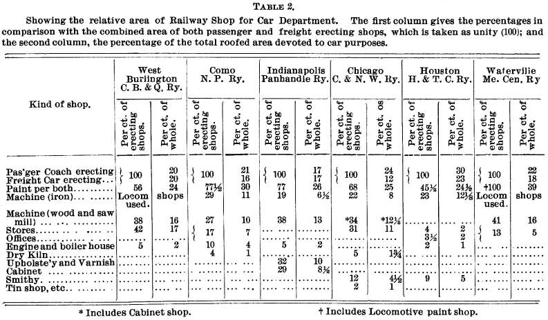
Table No. 2 gives from recent practice, the relative
area of some American car shops, the percentages being shown in
double columns (as explained for Table 1).
The annular form of car shop with radial tracks is occasionally
used in America, requiring a turntable of exceptional dimensions,
usually 100 ft. in diameter, to permit not only a coach or two
freight cars, but also the small tank locomotive doing the shunting,
to turn upon it. A large amount of shunting is required in and
about a freight car repair shop, due to the short time occupied
in an average repair to a car, and the passage of each vehicle
over a turntable adds both to the time and to the cost of shunting.
The supposed difficulty in utilizing the whole floor space
of a longitudinal shop, and which the annular shop was designed
to avoid, is the delay in taking out a string of cars until all
are finished, thus sometimes keeping the workmen idle waiting
for work. However, even in one of the best examples of the annular
shop, that of the Pennsylvania Railway at Altoona, the radial
tracks were intended to be three cars long, and therefore some
sorting and dividing of cars is necessary before they can be put
in, and all that the other type, with its long tracks, requires
is that this classing together of cars be done with a little more
care and judgment, so that the whole string will be finished and
ready to shunt out at the same time. There are good points in
favor of the annular shop, if it is intended exclusively for new
construction, one being the ease and rapidity with which material
on trolleys is delivered close to the workmen.
However, the author would endorse the longitudinal freight
car shop, which is of the simplest construction, often wide enough
for six or seven parallel tracks, and from 200 to 500 ft. long.
The welts, of brick or wood, the roof almost flat (the slope each
way from middle being about one in twelve) and supported by timber
posts 8 or 9 ins. sq. The posts, though numerous, do not seriously
interfere with the work The roof covering is cut for numerous
skylights, gable-shaped, and of quick pitch. Usually the floor
is flush, that is, neither track pits, cranes, nor hoists are
provided. The car bodies to be lifted being light and bulky, and
requiring in many cases to be sustained after they are lifted,
it is found best to use quick-moving hand jacks to lift, and dons
or trestles to effectively support them, while the men do the
work of repairing.
Numerous trolly roads cross the building in both directions,
their union at intersection being made by cast-iron turntables
revolving on a central spindle. These tables may be of two castings,
a base, forming both pit and foundation, and a revolving top with
socket on under side.
This building and its contents are so liable to destruction
by fire as to justify large water pipes and numerous fire-hose
hydrants within it as well as without.
There is no real economy in the endeavor to repair freight
cars and passenger coaches under one roof. The work is so different
in character that men can rarely be transferred from one class
to the other, and the dirt and dust inseparable from the cars
should be kept away from the coaches. When both classes of repairs
are done in the same building, it is imperative that a shop free
from dust and at a higher temperature be used for painting and
varnishing coaches in. It is often built directly opposite to
the car repair shop, with a transfer table between. Here, as elsewhere,
entrance from both ends of a longitudinal shop is desirable, and
hag been obtained in many recent designs.
At the Como workshops on the Union Pacific Railway, each stall
in the paint shop is provided with an electric call bell, communicating
through signal-code both with the foreman's office and the paint
store, which latter building, as in all railway shops, is detached,
and as far as possible of fireproof construction. Often it is
provided with an under ground cellar for the storage of all inflammable
fluid. According to the best practice, only one man at a time
is allowed to work in this house mixing the paints and blending
the colors, and in some cases the brushes and other tools used
by the workmen are stored here and only issued as required. It
is a "paint tool-room" in which much the same system
prevails as in the "machine tool-room."
WARMING AND VENTILATION.
Paint shops need special facilities for warming and ventilation.
A successful arrangement is the use of a fan to draw air through
a nest of small steam pipes, and then to force the warmed air
into a light galvanized iron tube, from which it is passed into
overhead branch pipes and delivered through slide-gratings below,
the slides being within the control of the workmen.
At Columbus the paint shop is 75 by 135 ft., containing 272,665
cu. ft., and the steam pipes have a surface of 1,034 ft., or one
superficial ft. per 263 cu. ft. The fan has a maximum delivery
of 218 cu. ft., and has been run as high as 200 revolutions per
minute. The three main pipes leading from it are 30 and 24 in.
diameter; and the smallest delivery pipe is 8 in. diameter. The
air is used over and over again, and so used, it is said, without
any annoyance from the odor of the paint. Running the fan during
working hours only reduces the time in which the paint dries by
one-tenth. The apparatus is widely adjustable to suit the varying
temperatures, as either live or exhaust steam can be turned into
the heater pipes, and its amount regulated; or the speed of the
fan can be varied within large limits, to which end a separate
engine 6 in. by 9 in. stroke, with steam at 80 lbs. pressure is
used to give it motion. The success that attended this experiment
has justified Mr. E. B. WALL in extending this system at Columbus
to the machine, boiler, and blacksmith shops and the annular car
repair shop. At Bloomington the new locomotive erecting shop is
warmed in this manner. The exhaust steam from the stationary engine
is passed into an old boiler, through the tubes of which the air
is drawn, and then delivered into underground pipes, the outlet
gratings being at the floor level.
This hot air method was in 1886 adopted for widely scattered
shops at Cleveland, O., by Mr. J. WALKER (see his communication
to the Civil Engineers' Club of Cleveland, Sept. 13, 1881). He
used a fan 10 ft. outside diameter with engine 6 in. by 9 in.,
running from 50 to 275 revolutions per minute, the fan outlet
being 42 in. sq. With underground conduits across the yards, he
finds that it requires 1 superficial foot of steam pipe for each
100 cu. ft. of shop space, the initial air temperature when entering
the fan varying from 100° to 180° Fahr. The conduits are
of sewer pipe, the largest diameter of any main being 24 in.,
and they are trapped so as to get rid of any water that might
gather. After the ground had dried, there was no appreciable loss
by radiation from the buried mains. This arrangement permits the
fan and heater to be kept within the boiler house, and the water
of condensation to be returned to the boiler at a temperature
averaging 180°; but the air is not used a second time, which
explains the increased ratio of pipe heating surface per cubic
foot of space to be warmed. However, the shops and foundry are
kept clear of smoke, the health of the men is all that can be
desired, and the system can as readily be adapted to cooling in
summer as to warming in winter.
Illustrative longitudinal types of coach and car shops may
be seen at the Grand Trunk Railway Works, Point St. Charles, and
one of the worst specimens of the circular shop, although a very
showy building, at Mount Clare on the Baltimore & Ohio Railway.
It is 235 ft. inside diameter and fully 114 ft. to top of dome,
yet has only space for 21 coach stalls and an inlet track.
GENERAL DISPOSITION of SHOPS.
What may be called the typical grouping of American railway
shops is to place them parallel with each other, and with their
longitudinal axis at right angles to the main track (or chief
yard siding), with several traverser beds and tables between them.
In other words, the shops lie side by side with their gable ends
facing the track.
The stalls (or shop tracks) being at right angles to the length
of the buildings, or parallel with the main track, if the traversers
are set in line with each other, a passage through from shop to
shop is provided; that is, it makes a through temporary passage
parallel with main track.
Good examples of this arrangement are the St. Paul workshops
of the Chicago, St. Paul & Kansas City, and the West Chicago
workshops of the Chicago & Northwestern (see engraving), and
it has advantages, one of the chief being that if sufficient width
of land is secured, it permits extensions in length to be built
uniform with the existing buildings, without interfering with
the ordinary railway work; and when the addition is completed,
does not necessarily require a resetting of the machines, shafting
or warming pipes, etc., in order to fully utilize the added space.
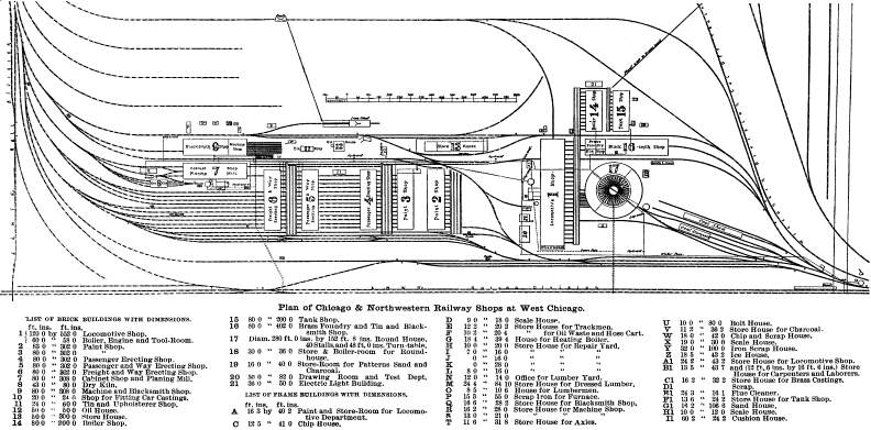
For Full Size
Click Here
Until the use of electrically moved overhead cranes changes
the shape and size of such shops, does away with the traverser,
and alters their relationship to the main track, this grouping
will probably continue to be adopted. It necessitates the pug
chase of a block of land, wide but not long.
One of its most prominent defects is the necessity for skylights.
The side walls are so cut up by large stall entrance doors, almost
filling the wall panel, that there is little space for side windows
except those of limited size, framed into the leaves of the doors;
while, as the door openings cannot be kept quite close and tight,
in latitudes where cold high winds prevail, these numerous inlets
interfere with the comfort and efficiency of the workmen. How
ever, for a correspondingly brief period in mid summer, the doors
thrown wide open are an appreciated luxury, compensating in some
measure for the winter inconvenience.
So grouped, the buildings are well isolated in case of fire,
as not only does the width of the traverser pit intervene, but
in addition, there is a space of from 10 to 15 ft. between wall
and edge of bed, ordinarily utilized in the storage of wheels
and trucks.
A neat and compact arrangement was adopted for the shops built
in the summer of 1887 for the Maine Central Railroad at Waterville,
Me. The buildings are set on each side of a single traverser bed,
and occupy but little land. The arrangement will not prove elastic
should extensions become necessary.
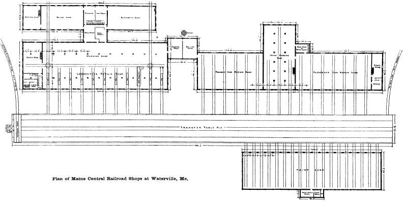
For Full Size
Click Here
In new works, buildings are rarely set closer than 50 ft. apart;
40 ft. will usually fulfill the requirements of the fire insurance
inspection, while a distance of 35 ft. has been proved to be far
too close for efficient side light even with one-storied buildings.
The new shops of the Panhandle Railway are set wide apart,
with many large trees left standing in between them, forming a
pleasing feature to the eye; but even in this country of cheap
land, few railways subordinate considerations of economy to the
gratification of an aesthetic taste, making the workshops ornaments
in a natural park.
In vivid contrast to buildings spaced in this liberal manner
are the works of the London & Southwestern Railway at Nine
Elms, London, where the space under the viaduct carrying the four-track
main line has to be utilized for shop room.
Freedom from snow, giving a wide liberty in roof design, simplifies
the grouping of shops in Europe; and in Germany a style of shop
not uncommon is one having a continued hip and furrow roof covering
about 17 bays. With sufficient glass (part of it movable) there
is no reasonable limit to the amount of light and fresh air admitted,
and when artificial heat is necessary, the lack of height in the
building is a help to the warming. In many instances the establishment
is under one roof, as at St. Rollox on the Caledonian Railway,
Scotland the area being 12 acres; or the locomotive shops are
under the one roof and the car shops under another The number
of trolly tracks and power cranes, and the compact setting, makes
the handling of material and work a simple matter.
In plan, the tendency is for the longitudinal axis of the main
building, and the stall tracks, to run parallel with the main
track, so that the plot of land required is long and narrow, as
for instance in the Horwich new shops for the Lancashire &
Yorkshire Railway, the erecting shop of 200 engines capacity,
with 6 parallel tracks and a central machine bay, is 1,520 ft.
long—almost one-third of a mile:
Although in Canada and the Northern States, shop roofs cannot
be a continuous duplication of small pieces, yet the main buildings
may have duplicate roofs, that is, a uniform span may be adopted
for erecting machine, boiler, car and paint shops, etc. The Pennsylvania
Railway has so designed and built combined shops that the portion
originally used as car shops can at slight expense be adapted
for locomotive repairs, when the growth in business shall justify
the increase of this section and the removal of the car department
to another location.
On the general question of grouping, the late A. L. HOLLEY
may be quoted. Speaking more particularly of steel works, he remarks.
"Joliet is perhaps the only establishment where railroads
were laid out first and buildings made to fit; and in designing
works, provision only can be made for minimum amount of rehandling
and hard labor, by going over all the operations on paper by different
arrangements again and again, and not trusting to general ideas
to be worked out when it is too late to move a building that happens
to be in the way."
For intercommunication, not only between the chief offices
and foremen's offices, but also between shop and shop, and each
bench and the tool room, electric bells, telephone service, and
displayed signals, to call persons moving about through the works
to the nearest telephone, are daily receiving more general adoption,
and their usefulness is so marked that a single experiment with
them is sure to result in their permanent use.
DISCUSSION.
Mr. F. BROWN, of the Canadian Pacific, questioned Mr. BARNETT'S
statement as to the length of time required for engine repairs.
Mr. BROWN said that in a divisional repair shop the limit of time
for heavy repairs should be 60 days. This, however, does not mean
rebuilding an engine. A medium repair should not take more than
30 days, and light repairs 7 to 14 days. In the main shop
of a railroad company this time should be reduced to 42
days for heavy repairs and 21 days for medium repairs, as a maximum,
while light and specific repairs might occupy 3 to 14 days.
In June, 1886, the Canadian Pacific Railroad shops at Montreal
were ordered to build some new class consolidation engines. Complete
working drawings had to be made and some material imported; but
the first engine was on the road in just 90 days after the receipt
of the order. A year later, on an order for some 17 in. x 24 in.
engines, the first engine made her trial trip 77 days after the
receipt of the order.
Mr. WALLIS, of the Grand Trunk, endorsed the author's remarks
commending the longitudinal type of engine shed. The Grand Trunk
longitudinal shed at Montreal contains five tracks, and has a
capacity of 25 engines. With the iron turntable outside, water
service and steam heating pipes and appliances, sand house, and
tool store, it cost about $50,000, or $2,000 per engine accommodated.
Another advantage of the longitudinal type of shed was the
rapidity with which engines could be moved out in case of fire.
The fact that all entrance to and exit from the round type of
house depended on one turntable was not infrequently the cause
of much annoying delay. Again, in severe weather, such a house
as the one at Montreal could hold one extra engine on each track,
by crowding the others very closely. In a roundhouse such extra
capacity could not be obtained. He thought it likely that the
first cost of the round type of house per engine accommodated
was rather less than that of the longitudinal type, and that in
laying out yards it was generally more convenient to spare the
block of land required for a roundhouse than the long, narrow
strip required for a longitudinal shed. Skylights in an engine
house were never satisfactory; they subjected the roof to unnecessary
chances of decay and were difficult to keep clean. The light from
side windows was much more evenly distributed in the round type
of house.
Mr. J. HARKOM endorsed the suggestion of the author that repair
shops should generally be arranged on the rectangular system.
The sorting of cars had to be done in any event, and the work
should be so systematized that whole trains of completed cars
would be turned out together. More cars could be worked upon in
a longitudinal shop than in a shop of the same area of the other
type. Shops should be so arranged that the tracks to them will
be always open, and cars can be readily delivered from the works
to the main line.
In regard to stores Mr. HARKOM made the following suggestion:—
The fact that in large works every time
a piece of work is handled it costs more or less money, should
never be lost sight of; and that system is the best which provides
for the fewest handlings outside these absolutely necessary for
manufacture and treatment in the different processes.
All material should be delivered at the stores, weighed, measured,
and tested by officials of that department. The stores should
be located in such a position that easy access can be had to them
by trucks and wagons.
The object of the works being to turn out finished articles
in the shape of engines and cars, the stores should be placed
between the two sets of shops, with the idea that raw material
supplied from them should issue in the shape of finished work
at the opposite end of each set of shops.
The shops handling the heaviest material should be nearest
the stores; therefore the first shops in the locomotive series
should be the boiler shop, then the smith's shop, the machine
shop, wheel shop, erecting shop, tin shop, and paint shop in the
order in which they are named .
Lumber being a special article of largo bulk, and necessitating
a large stock, should be kept in its own yard a considerable distance
from the works; but access to it should be readily had from the
main trucks. The position of the foundry is much the same as that
of the stores; and it should be located as near to both locomotive
and car shops as possible.
Two tracks should run the whole length of the work, with frequent
cross-over switches and connection to the transfer table in boiler
and erecting shops, if such is used: and by the simple precaution,
in first laying out the shops, of establishing the floor levels
two feet above the mean out-door level, which will ensure dry
ground around the shops, the traversers may be worked out of doors,
even in Canada, so saving the extra roof referred to by the author.
Where the traversers can thus be used, it is, in the opinion
of the writer, far preferable to the overhead system, which calls
for construction of the shops in a much more expensive manner
than the traverser system.
Mr. HARKOM favored the distribution of power from a central
boiler house by steam pipes rather than from large engines by
ropes, belting, shafting, etc. The shops for the manufacture of
permanent way material should be set somewhat by themselves. The
locomotive yard should be on the same side as the erecting shops,
to which two tracks should lead, one for the delivery of new boilers
and engines under repair, and the other for the exit of the completed
engines en route to the paint shop. Regarding roofs for
engine-houses, he commended a double roof as preventing condensation
and the formation of icicles in cold weather, and described as
follows a roof erected by him in 1888:—
The old roof was a flat one, a little over
half an acre in extent, covered with the ordinary gravel and tar
felt.
The gravel was all scraped off the felt, which was patched
and repaired with Sparham roofing material, where such was necessary,
after which 4-in. scantlings were laid, and common boards laid
on them, the ends being partially closed by overlapping at eaves,
in order not to entirely prevent circulation. The building was
then handed over to the roofers, who readily gave a ten years'
guarantee for the roof, the contractor telling the writer that
his experience of double roofs was that he had no repairs to do
to them, the action of the weather, snow, ice, etc., being practically
reduced to the very lowest possible point.
For slate on pitch roofs, excellent results have been obtained
by laying the slates on strips pitched the right distance apart,
three winters at Athabaska having failed to show an icicle on
the eaves, and others since built give the same result. Slate
on a roof with pitch of 1 to 3½ had been successfully laid
on fuel sheds, and this winter he has seen the snow slide off
that roof.
On the material and construction of ventilators, Mr. HARKOM
said:—
The use of iron has the effect in cold weather
of creating a conflict of currents in all iron ventilators, which
the writer has found is not done when wood is used, the sides
being doubled and an air space left around them.
The painting of the inside with fireproof paint makes them
perfectly safe, while a down draught never takes place in them.
The writer has in cold weather seen vapor descend on an iron ventilator,
and directly pass to and out of a ventilator made as described
of wood. A number of these are in use on engine sheds, placed
there under the writer's supervision, with good results; and they
are in use on the roofs of the smith's shop and foundry of the
Grand Trunk Railway at Montreal.
Mr. ATKINSON referred to the subject of foundations, and thought
that iron pillars run down below the floor level would be liable
to rust and become weakened in made ground.
Some track pits he had seen were of very bad construction.
They were often made with a concave floor, so that the workmen
stood in water unless there was a good system of drainage. He
advocated a convex floor, with a brick setdown at each side about
4 ins. deep to act as a gutter.
When the round type of engine house was used, he favored a
roof with outward slope rather than inward, as proposed by the
author. The system of roof covering adopted by Mr. HARKOM would
give great freedom from the nuisance of icicles.
As to the use of cranes, he was heartily in favor of the overhead
traveling crane. They were such labor-saving appliances that a
break-down with one was as bad as having 20 or 30 men away from
the shop. The cranes of this type, under Mr. ATKINSON's charge
at the Canadian Pacific R. R. shops, have a span of 55 ft. and
a capacity of 25 tons. They cost about $3,000 f. o. b. at Liverpool.
They are driven by 1¼ in. manila rope, running at a speed
of 2,500 ft. per minute. The makers were Craven Bros., of Manchester.
A single-rail crane of Ramsbottom make, in use by Mr. ATKINSON,
gives also much satisfaction. It has a radius of 13 ft. and a
capacity of 3 tons.
As to the foundry, he did not favor the L
type of building proposed by the author, since it would interfere
with the use of an overhead crane, and would also give a large
expense for wall and roof in proportion to the space occupied.
In the smith's shops, no doubt, many were using the central
smoke flue referred to in the paper. He had got rid of a smoky
shop by making the roof a better type of ventilator. The ordinary
single-span roof with a clere-story open below, and having louvre
sides, was not adapted for getting rid of smoke. The louvres allowed
snow to blow in, and the air could not get out freely, causing
the shop to become full of smoke. He roofed up the principals
of the main roof with boarding to within about 2 ft. of the ridge-pole,
leaving the clere-story open at each side by taking out the louvres,
and made a ventilator of it along the whole length of the shop.
He came to think of this method by observing the new Canadian
Pacific Railway station on Dominion Square, which had a clere-story
roof open at the bottom, and with which there was invariably a
great deposit of snow, while the smoke did not get out as it should
do. If the roof were boarded up to within a short distance, of
the center, the smoke would pass out through the opening.
The roof which he altered was held up by ordinary supports,
and boarded across in sections of about 15 ft. When there was
no wind, the heated air went out of its own accord, while the
cross boarding prevented the wind going down into the shop, no
matter which way it might be blowing. He had an excessive amount
of smoke in one of his shops from two large furnaces in addition
to small ones, and the first result of his arrangement was the
removal of the sulphur, which had given them much trouble, the
smoke following it away. He had not attempted to reduce the amount
of suction, simply leaving it open. The clere-story was left exactly
as before, and he boarded up within about 2 ft. from the center
of the ridge-pole.
While speaking upon this subject, he said he intended to try
his system of ventilation in a shop which it was necessary to
keep warm at night, and in doing so he would put rising and lowering
doors, one on each side, so that when either was raised it would
act as a deflector. In this way he felt sure he could clear a
smoky shop in twenty minutes.
Regarding floors, he favored plank for both machine and erecting
shop; but if earth was used he advised covering it with a mixture
of iron borings and sal-ammoniac, which would in time become as
hard as asphalt. .
He accounted for the difference in the length of time mentioned
by the author as necessary for repairs and that set by Mr. BROWN
by the excellent equipment of the Canadian Pacific shops, especially
in the matter of cranes, enabling them to turn out work very rapidly.
About half the Canadian Pacific locomotives were built abroad,
and these came in for repairs as often as engines built by the
company.
Mr. MACPHERSON referred to the trouble with icicles on engine
house roofs, and said he had got rid of them at a nominal expense
in an engine house erected under his supervision at Hochelaga
in 1886 by building a few pieces of 2-in. diameter iron pipe into
and through the walls just under the roof at the gables.
Several brick engine houses built on the Canadian Pacific Railway,
previous to this, without these air holes, have given great trouble,
on account of the icicles backing the water up under the eaves
and ruining the walls. The one referred to at Hochelaga has given
no trouble in this respect, and the icicle formation is very slight.
At the same place may be seen a 65-ft. wrought-iron turntable,
which length does away with the frogs leading to the engine stalls;
the angle being 9° between centre of pits.
He preferred the radial type of engine house to the longitudinal
at all points where time was an object, and thought that a turntable
was a much quicker means of turning an engine than a Y.
The sides of the double roof on the Montreal station of the Canadian
Pacific are not finished. The clere-story is to have small windows
all around, which will be closed by a small chain, running along
the side of the roof, in snow storms. The slat system could not
keep snow out without keeping smoke in.
Mr. BARNETT replied to several of the criticisms. He thought
that if iron pillars were properly coated with tar, they could
be carried down below floor level without any danger resulting
from corrosion.
As to the difference of opinion about the length of time required
for repairs, much seemed to be due to the difficulty of accurately
classifying the various jobs as heavy, medium, light, etc. His
figures were taken from the actual work done on the Grand Trunk
shops at Stratford. In one year 76 engines received heavy repairs,
requiring an average of 62 days; 21 engines received medium repairs,
occupying an average of 29 days; and 37 engines received specific
and light repairs, occupying an average of 20 days.
Since that date the Stratford shops had been enlarged and re-equipped,
and in 6 weeks past the work done had been as follows: heavy repairs,
11 engines, average 92 days; medium repairs, 12 engines, average
32 days; specific and light repairs, 32 engines, average 23 days.
In examining to see what per cent. of his locomotives were at
any time actually available for traffic, he found that there was
generally a few days lost from the time an engine left the erecting
shop until she was ready for traffic. Engines sometimes had to
wait for pit room or for painting, and he was of the opinion that
4 to 5 per cent. of the engines would neither be in the repair
shop occupying pit room nor in the roundhouse ready for traffic.
He referred to the great change which the general introduction
of cranes had caused in the economical arrangement of shops. It
was formerly considered necessary to place all the large tools
handling heavy pieces near each other. Now that overhead cranes
could transfer a ten-ton weight as easily as a two-ton, the tendency
was to group together machines of the same kind and thus make
one attendant able to do the greatest possible amount of work.
In the L shaped building, which
he recommended for a foundry, a single jib crane could be made
to cover nearly the whole area of both wings of the building.
If an overhead traveling crane was used, of course a square or
rectangular building was the best type.
Mr. MACPHERSON's simple plan for avoiding icicles on engine-house
roofs, he considered most valuable. He supposed the current of
warm air from the interior melted the icicles or prevented their
formation.
He emphasized again the advantages of the rectangular type
of locomotive shed. The English railway official before referred
to, who handled 400 engines daily, claimed that with the rectangular
shed he could turn his engines outside and get them in exactly
the right position to take out their next trains shortly after
their arrival and nine or ten hours before they were due outwards
again; whereas with an annular engine house, he could not have
got the engines turned and into position again at certain busy
hours of the day without taking them out of the engine house and
leaving them outside, which would requite extra siding room where
space was valuable.
An incident was related where a central turntable in an annular
engine house broke down at 2 o'clock in the morning just before
the engines inside were due to leave. The engines were shut up
for about ten hours, throwing the traffic department in great
disorder. Such serious mishaps were rare; but a district officer
seldom got through a winter without some failure to a turntable.
A turntable was necessary with the longitudinal type of shed,
but its failure did not lock the engines in the shed.
Mr. HARKOM had referred to the ideal grouping of shops. The
author had considered such a mode of discussing the question,
but had finally decided that the paper would be of less interest
and value than if it had dealt with the work done under the limitations
of actual practice.
RR Structures | Contents
Page
|


