CAR TRANSFER BRIDGE AT WEST NORFOLK,
VA.
ATLANTIC & DANVILLE R. R.
Engineering News—September 19, 1895
Car ferries are very commonly used for the transfer of railway
cars at harbors from the railway piers to private docks and yards,
and also for transferring trains across rivers and the great lakes
to connect certain railways forming through transportation routes.
In order to transfer the cars from the pier to the barge or steamer,
a hinged bridge is necessary, with means for adjusting the free
end to coincide with the level of the track on barges of different
heights and at different stages of the tide. This adjustment is
effected by means of chains passing over pulleys in the top of
a gallows frame over the free end of the bridge. Such bridges
may be divided into two classes: the first having a pontoon under
the end, and the second being supported entirely by the chains,
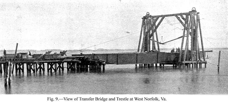
the latter being in many ways preferable. The accompanying cuts
represent a bridge of the latter type, built at West Norfolk,
Va., for the terminal improvements of the Atlantic & Danville
R. R., and we are indebted to Mr. Philip Aylett, who was Resident
Engineer on the work, for drawings of the structure.
The bridge is situated about 450 ft. from the shore, being
approached by a timber trestle over a sandy flat, which is bare
at low tide and covered with about 3 ft. of water at ordinary
high tide. The outer end of the bridge is 250 ft. from the channel
of the eastern branch of the Elizabeth River, and 200 ft. from
the Port Warden's line. By this arrangement the dredging of a
ferry slip 700 ft. in length was avoided. The present slip is
250 ft. long, 50 ft. wide at the end of the bridge, and 150 ft.
where it meets the channel. About 40,000 cu. yds. of material
were dredged, giving a depth of 13 ft. of water at low tide. The
fender and guide piling extend along both sides of the slip from
the gallows frame to the Port Warden's line.
The approach trestle has bents 14 ft. c. to c., each bent having
three piles 4 ft. apart, except that at about 170 ft. from the
bridge the trestle widens out for two tracks, the main track being
carried straight on to the bridge, and the second track turning
out from the main track, the point of the switch being 170 ft.
from the pivot pins of the bridge. The turnout curve is 17°
and 56.5 ft. long, then reversing and entering a tangent 13 ft.
from center of main track by a curve of 9° 29' and 98.6 ft.
long. This arrangement gives a minimum length of siding and 15
ft. of tangent before entering the bridge, but an easy turnout
is of more importance then a short siding. The bents have caps
12 x 12 ins., which carry stringers 8 x 15 ins. and 28 ft. long,
upon which are laid the ties. In order to shorten the trestle
approach, the shore end is on a 10° curve for a distance of
200 ft., the outer rail being elevated by 3-in. raising blocks.
The trestle piles and abutment piles are of unbarked cypress,
the former ranging from 30 ft. to 50 ft. in length, according
to the nature of the soil penetrated, and the latter 50 ft. long,
18 ins. diameter at the butt and tapering to 8 ins. The foundation
piles for the gallows frame are of creosoted pine, 50 ft. long.
The piles for the abutment and the gallows frame have 12 x 12-in.
creosoted Georgia pine caps, drift bolted to each pile. Virginia
yellow pine ties treated with 8 to 10 lbs. of creosote per cu.
ft., are used in the foundation for the gallows frame, and the
frame itself is of Georgia pine. The heads of piles and all joints
between caps, etc., are thoroughly coated with creosote.
The arrangement for adjusting the height of the free end of
the bridge is novel, and is specially designed to provide for
the irregular loading of the bridge by a car on one track only,
which thus depresses one side of the bridge more than the other.
For this purpose each side of the end is counterbalanced independently.
Thus, in the cross-section, Fig.
2, the cable secured to a block on the top of the gallows
frame by a U-bolt at A, passes down to the geared pulley B, across
the bridge (raising through 6-in. holes in the web plates of the
girders), round a loose pulley opposite B, and then up to the
46-in. loose pulley C on the gallows frame, and down to the counterweight
D. About a foot behind this cable is another, secured to the top
of the gallows frame by a U-bolt at E, passing round the geared
pulley F, across the bridge (through holes 11 ins. from the center
of those for the other cable), round a loose pulley opposite F,
and then up to the loose pulley G on the gallows frame and down
to the counterweight H. The wheels C and G are set at an angle,
so that the cables clear each other, as shown in Fig. 3. The friction of each cable on
its geared wheel is such that either side of the bridge can be
raised or lowered by turning the hand gearing, so that the bridge
tilts sideways with the opposite geared pulley as a pivot. In
use the gearing is free to revolve under any force exerted at
the end of the bridge resting on the barge. The arrangement of
the gearing is shown in Fig.
4.
The two counterweights are equal to half the suspended weight
of the bridge, their weight aggregating 50,000 lbs. to balance
100,000 lbs. of suspended weight, and by the gearing the counterweights
are made to exactly balance the bridge, so that the same amount
of power is required to lower as to raise the end. The bridge
will thus remain in any position to which it is adjusted, and
when the barge is loaded it can be withdrawn without any further
adjustment of the bridge by the gearing. Each counterweight is
a cylinder 3 ft. 6 ins. inside diameter, of three courses of ¼-in.
plate and a dished bottom of 7-16 in. plate, all put together
with 5/8-in. rivets. The bottom has a small hole for drainage.
The total height is 14 ft. 10½ ins. Inside cross-plates
near the top of the cylinder carry the 1¾-in. U-bolts,
30 ins. long, to which is attached the iron loop of the hoisting
cable. These cables are of 1¼ ins. diameter, of cast steel
wire, and are 119 ft. long over the loop ends.
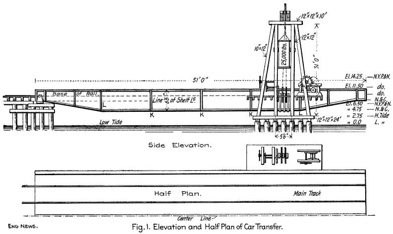
By means of the gearing the bridge can be adjusted to any ordinary
barge, whether level or careened, and the various heights of barges
used in connection with this transfer are shown in Fig. 1, the
New York, Philadelphia & Norfolk R. R. having barges of three
different heights, and the Atlantic & Danville R. R. having
its barges so constructed as to be even with the bridge track
when the bridge is level longitudinally. The free end of the bridge
has a range of movement of 10 ft.
The bridge consists of three plate girders, 51 ft. long, or
50 ft. long from the pivot pins to the outer end, 6 ft. 6 ins.
deep, and spaced 13 ft. 4 ins. apart c. to c. They are designed
for a dead load of 600 lbs. per lin. ft., and a live load of 1,500
lbs. per lin. ft. The maximum bending stress is equal to 25,500,000
inch-pounds, and the fiber stress is 9,600 lbs. per sq. in. Each
girder is built up of 8 chord plates, 9-16 x 12 ins.; 4 chord
angle irons, 23-32 x 5 x 3½ ins., weighing 18 lbs. per
ft., and one web plate, ¼ x 78 ins. At a depth of 2 ft.
9 ins. below the top chord are longitudinal shelf angles 5-16
x 4 x 3 ins., riveted to one side of the web plate of each outer
girder and to both sides of the middle girder, these angles carrying
the ties. At the shore or pivot end the depth of the girders is
reduced to 2 ft. 10½ ins., and each girder has a horizontal
pivot pin 4 15-16 ins. diameter and 5-and-3/8-ins. long at the
bearing, with a neck 4 ins. diameter and 1½ ins. wide at
each end, and each pin having two 4-in. Lomas nuts. The pins and
bearings are shown in Fig.
5. At the outer end the girders are 3 ft. 6 ins. deep, connected
by a plate girder, as shown in Fig.
6.
There are two main cross-girders of the form shown in Fig. 7, which are spaced 4 ft. 6 ins
apart, and carry the gearing. An extension of the upper members
of these girders, 5 ft. 1½ ins. long, is riveted to the
outside of the outer main girders, and carries the platform flow
the machinery. The lifting power is transmitted directly to the
lower members of these cross-girders (which members are under
the bottom chords of the main girders) by means of eyebars 2 ins.
square, having looped ends which embrace 6¾-in. pins in
the upper members and 4-and-15-16-in. pins in the lower members.
The gearing for the barge connections is supported upon four ties,
which project through apertures 8 ins. wide, 12 ins. high and
24 ins. apart, cut in the webs of the outer main girders. The
toggle bars and barge connections are so arranged that any motion
of the barge, whether horizontal or vertical, is communicated
to the bridge. The latches are bars 5 ins. square, moved by means
of a hand wheel and gearing.
The necessary flexibility of the bridge to withstand the effect
of the barges careening when loaded on one side only, is provided
for by placing the lateral bracing in the neutral axis of the
main girders. Secondary stresses are thus avoided, and any given
cross-section remains rectangular, while considerable freedom
to twist is allowed. At the three panel points marked K, K, K,
on Fig. 1, are horizontal, transverse angles 3/8 x 3 x 3 ins.,
level with the shelf angles, while at the two panel points marked
L, L, is the vertical transverse bracing shown in Fig. 8. In the five panels formed by
K, K, K, and the top chords of L, L, is the horizontal diagonal
bracing, consisting of angles 5-16 x 3 x 3 ins., with 5-16-in.
junction or intersection plates.
The superstructure was designed by Mr. Charles C. Wentworth,
M. Am. Soc. C. E., and the terminal improvements (including this
structure) were constructed under the supervision of Mr. W. B.
Causey, Engineer of Maintenance of Way of the railway. Mr. Philip
Aylett was Resident Engineer in charge of construction, and Mr.
Jos. Causey was Assistant Resident Engineer. The superstructure
was built at the works of the American Bridge & Iron Co.,
Roanoke, Va. Messrs. Rutherford & Brown, of New York, were
the contractors for the piling and dredging, the Delaware Construction
Co., of Wilmington, Del., being the subcontractor.
RR Structures
| Contents Page
|


