A Text Book on Civil Engineering
Copyright 1897, 1898, 1899 by The Colliery Engineer Company
WATER STATIONS.
1815. Water stations are points along a railroad where
the engines stop to take in water. Their distance apart will depend
mainly upon the amount of the traffic, but somewhat upon the grades.
On roads with a light traffic, water stations at intervals of
15 miles will meet every requirement, while roads with a heavy
traffic and frequent trains may require them at every 5 or 6 miles.
They usually consist of large wooden tubs placed upon a strong
framework, supported by heavy pillars which rest upon a foundation
of masonry. The tubs are generally circular in form, the bottom
diameter being a few inches larger than that of the top diameter,
in order that the iron hoops may drive tight. White pine, cedar,
and redwood are the varieties of timber principally used in the
manufacture of tanks. The staves are planed by machinery specially
designed to give them the proper bevel, so that when set up the
joints are close and water-tight. The staves are fastened together
at the top with a single dowel between each two, merely to hold
them in place while being, set up. The pieces forming the bottom
of the tank are doweled together and fit into a groove about I
inch in depth, which is cut into the staves to receive them. The
hoops are fastened together with lugs which grip the two ends
of the hoop. The two lugs are united by a bolt threaded at both
ends and fitted with nuts. By screwing up these nuts, a strain
is put upon the hoop. The hoops are first nearly driven to place;
the lugs are then tightened with a wrench, after which the driving
is finished.
Railroad water tanks hold from 20,000 to 40,000 gallons. A
common size is 16 ft. in diameter and 16 ft. in height, holding
about 21,000 gallons. All tanks holding above 200 barrels are
made from 3-in. stuff. This thickness is some what reduced by
planing. The bottom of the tank should be from 10 to 12 ft. above
the tops of the rails. It is a common practice to enclose the
tank in a framed structure, the foundation and post supports forming
the first story, and the tank, together with its covering, the
second story. Where the supply of water is pumped, the first story
is often used as a pump house, and a fire is usually maintained
in winter to prevent the freezing of the water. At division or
terminal points, where many engines are to be supplied, the tank
is made proportionately larger, and often two are placed together.
It is desirable to combine a coaling with a water station,
in order that an engine may take both fuel and water at the same
time. Such an arrangement is usually made at division points and
terminals, though it is not always practicable to place a water
tank and coaling station side by side.
A tender of coal will serve for several tankfuls of water,
so that coaling stations situated at division points, at intervals
of say 100 miles, will serve every requirement.
When the railroad has a double track, it is customary to place
a water tank on each side of the roadway, so that engines may
take water from either track.
The tank house should stand near the track, leaving only from
2 to 4 feet clearance for cars.
1816. Source of Water Supply.—The least expensive
and most satisfactory water supply is that obtained from either
springs or brooks which have sufficient elevation to deliver water
into the tank by gravity and so avoid the expense of pumping.
Clear, pure water, as free as possible from mineral matter in
solution, is greatly to be desired. If the stream from which the
supply is obtained is liable to become muddy from freshets, a
reservoir of suitable size should be constructed and kept constantly
full of clear water, so that, in case of a freshet, the flow of
the water into the reservoir may be stopped until the stream runs
clear.
Where spring water is used, and the supply in times of drought
is liable to run short, a reservoir of ample capacity should be
constructed, and the surplus water stored for future use.
When the source of supply is too low to be delivered by force
of gravity, resort is had to pumping. Formerly, horsepower was
used to a considerable extent for pumping, but of late years steam
and wind power have been exclusively employed. Pumping by wind
mills is the least expensive, and, but for occasional calms, the
most satisfactory. The only way to provide against a short supply
due to calms is to make the capacity of the water tanks adequate
for a number of days' supply. The tank has three pipes: an inlet
pipe by which the water enters the tank, a waste pipe for preventing
overflow, and a discharge, or feed-pipe, 7 or 8 inches in diameter,
in or near the bottom, through which the water flows to the tender
tank. The discharge pipe is from 8 to 10 feet long, and jointed
at the end which joins the tank, so that when the tender tank
is filled, the discharge pipe, acted upon by a counterweight,
swings either sideways or vertically on its hinge joint, out of
reach of the cars. The discharge pipe at its connection with the
tank is provided with a valve which has a lifting gate. Movement
is communicated to this gate by means of a lever, the short arm
of which is attached to the valve rod. The long arm of the lever
has a rope attached, which hangs within reach of the engineman.
When taking water, the discharge pipe is lowered and swung
over the water hole in the tender tank. The engineman then pulls
down on the lever. This action raises the valve stem and allows
the water to flow from the water tank into the tender tank. Tender
tanks hold from 2,500 to 3,500 gallons.
1817. Standard Water Tanks.—A general plan of a
standard water tank is given in Fig. 632. The foundation is shown in
plan at A; a plan of the arrangement of timbers composing
the tank seat or deck is shown at B, and a complete elevation
of the tank at C. The foundations should be of the most
substantial character, of well-dressed stone laid in cement mortar.
The foundation consists of either continuous walls laid at right
angles; upon which the sills are placed and the posts mortised
into them, or a pediment of pyramidal form is built for each post,
as shown in the figure. Each post is secured to its pediment by
a dowel 1 in. in diameter by 6 in. in length. The stone pediment
forms a very substantial foundation. It is effective in appearance
and does away with the sills, which are apt to decay from alternate
wetting and drying.
 The posts are connected together
by girts a, b, c, which are tenoned into the posts and
fastened with tree-nails. This connection is further strengthened
by 4 in. tie-rods d, e, f, which pass through each row
of posts, a cast washer being placed under the head and nut of
each tie-rod. Between each two rows of girts a series of X braces g, h, k is placed and
securely spiked to the posts and girts. The caps 1, m, n, o,
upon which the beams which compose the deck rest, are 12 in. x
12 in., and fastened to the posts by mortise and tenon. The deck
is composed of two sets of timbers laid at right angles to each
other. The first set, laid directly upon the posts, are 3 in.
x 12 in., and uniformly spaced. They are held together and strengthened
by bridging (see detail D) besides being spiked to the
caps. The second set of deck timbers are 4 in. x 6 in., and laid
at right angles to the floor-beams. They are spaced 19 in. center
to center, and extend to within 3 in. of the tank staves. They
are in direct contact with the bottom of the tank, and receive
the entire weight of the water contained in the tank without allowing
any of its weight to rest upon the staves. The deck is usually
made octagonal in form, and where the tank is not covered by a
house, the deck is made to project far enough from the tank (as
shown at E) to protect the foundation and timber supports
from the weather. The sides of the tank flare or batter outwards
at the rate of ½ in. to the foot, so that the hoops will
drive tight. The posts are connected together
by girts a, b, c, which are tenoned into the posts and
fastened with tree-nails. This connection is further strengthened
by 4 in. tie-rods d, e, f, which pass through each row
of posts, a cast washer being placed under the head and nut of
each tie-rod. Between each two rows of girts a series of X braces g, h, k is placed and
securely spiked to the posts and girts. The caps 1, m, n, o,
upon which the beams which compose the deck rest, are 12 in. x
12 in., and fastened to the posts by mortise and tenon. The deck
is composed of two sets of timbers laid at right angles to each
other. The first set, laid directly upon the posts, are 3 in.
x 12 in., and uniformly spaced. They are held together and strengthened
by bridging (see detail D) besides being spiked to the
caps. The second set of deck timbers are 4 in. x 6 in., and laid
at right angles to the floor-beams. They are spaced 19 in. center
to center, and extend to within 3 in. of the tank staves. They
are in direct contact with the bottom of the tank, and receive
the entire weight of the water contained in the tank without allowing
any of its weight to rest upon the staves. The deck is usually
made octagonal in form, and where the tank is not covered by a
house, the deck is made to project far enough from the tank (as
shown at E) to protect the foundation and timber supports
from the weather. The sides of the tank flare or batter outwards
at the rate of ½ in. to the foot, so that the hoops will
drive tight.
The discharge pipe p, when not in use, takes the position
shown in the figure, being held in that position by the weighted
ball g, which is attached to the chain r, running
through the sheaves s, and thence to its connection with
the discharge pipe. A cross-section of the track is shown at G,
the top of the rail being 12 ft. below the outlet of the discharge
pipe.
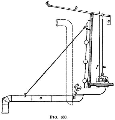
 The valve connection of the discharge
pipe with the tank is shown in Fig. 633. The connection may be
made either through the side or bottom of the tank. The bottom
valve connection is shown in the figure. The valve rod a is attached
to the short arm of the lever b. The weight c, attached
to the end of the short arm of the lever, holds the valve firmly
in place. A rope is attached to the end d of the long arm
of the lever and hangs within reach of the engineman. By pulling
down on this rope, the valve is raised, and the water flows through
the discharge pipe a to the tender tank. The vacuum pipe f admits
air to the discharge pipe after the valve comes to its seat, so
that the discharge pipe is quickly voided. The valve connection of the discharge
pipe with the tank is shown in Fig. 633. The connection may be
made either through the side or bottom of the tank. The bottom
valve connection is shown in the figure. The valve rod a is attached
to the short arm of the lever b. The weight c, attached
to the end of the short arm of the lever, holds the valve firmly
in place. A rope is attached to the end d of the long arm
of the lever and hangs within reach of the engineman. By pulling
down on this rope, the valve is raised, and the water flows through
the discharge pipe a to the tender tank. The vacuum pipe f admits
air to the discharge pipe after the valve comes to its seat, so
that the discharge pipe is quickly voided.
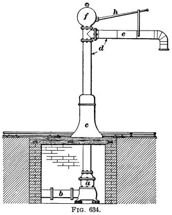
1818. Water Columns.—Where space is limited and
the head of water is sufficient, a water column (see Fig. 634)
is used in place of a tank. One advantage of a water column is
in its economy of space, as will be at once apparent. It can safely
be placed between the parallel tracks of a double-track road,
and serve engines on both tracks equally well.
This water column consists of a globe valve a, connecting
with the main water pipe b, and enclosed in a chamber of
brick masonry. This chamber is covered with a substantial floor
of timber, and forms the foundation for the pedestal c,
which supports the crane-shaped water column d. This column
is jointed at its connection with the pedestal, so that the discharge
pipe may be readily swung over the tender when taking water. The
cast-iron globe f (Fig. 635) is connected with the valve
disk by means 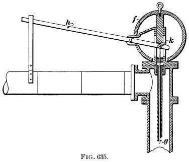 of the valve rod
g, and by its weight keeps the valve closed. When taking
water, the lever h is depressed. This causes the short
arm k of the lever to rise, and lifts the globe f.
The weight being thus removed from the valve, the disk is lifted
by the pressure of the water which flows through the discharge
pipe to the tender tank. of the valve rod
g, and by its weight keeps the valve closed. When taking
water, the lever h is depressed. This causes the short
arm k of the lever to rise, and lifts the globe f.
The weight being thus removed from the valve, the disk is lifted
by the pressure of the water which flows through the discharge
pipe to the tender tank.
Structures | Contents
Page
|


