ELECTRO-PNEUMATIC BLOCK SIGNAL SYSTEM
Scientific American—April 5, 1890
 The block system of running railroad
trains has been generally adopted in England. In this country
it has not yet come into very extensive use. As hitherto installed,
it requires the presence of an operative at the termination of
each block. The theory of its operation is simple. It consists
in the use of danger signals at the beginning of specified lengths
or blocks of track, each of which signals is to be kept at danger
when a train is on the block protected by it until the block in
question is free. In practice a block may be from 1,000 feet to
three miles in length. To facilitate traffic to the highest degree,
the length should not exceed one-half mile. To introduce the block
system, therefore, upon a line of road under the old system is
very expensive, owing to the number of men required to run it.
To reduce this expense there is a constant temptation to increase
the length of the blocks, thus making it less efficient. A system
which depends upon human vigilance can never be considered a perfect
one. In a recent issue we illustrated a mechanically worked interlocking
system of switches in use at the Grand Central Depot, New York,
which was constructed and installed by the Union Switch and Signal
Co., of Pittsburgh, Pa. This system represents the most advanced
type of mechanical appliance for railroad safety. In our present
issue we illustrate a plant recently erected by the same company
for the blocking of a track, in which the work is done by electricity
and pneumatic pressure combined, and in which all the operations
are automatic, human agency having no part whatever in the work.
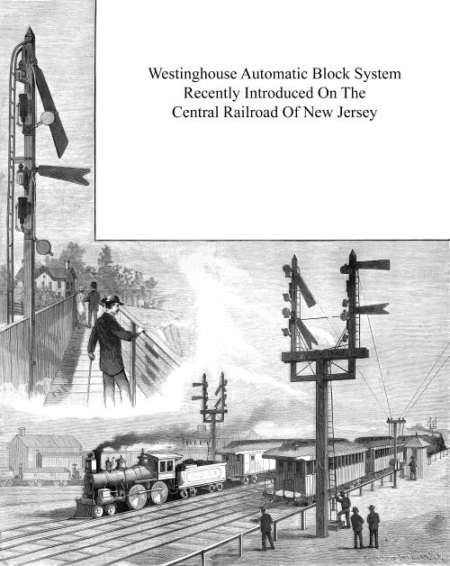
The system illustrated has recently been introduced upon the Central
Railroad of New Jersey, between Jersey City and Bergen Point.
It is a four-track road, and is traversed by a very large number
of trains daily. It has been found advisable to protect all classes
of traffic, and accordingly the system has been put in operation
on the four tracks. The block system of running railroad
trains has been generally adopted in England. In this country
it has not yet come into very extensive use. As hitherto installed,
it requires the presence of an operative at the termination of
each block. The theory of its operation is simple. It consists
in the use of danger signals at the beginning of specified lengths
or blocks of track, each of which signals is to be kept at danger
when a train is on the block protected by it until the block in
question is free. In practice a block may be from 1,000 feet to
three miles in length. To facilitate traffic to the highest degree,
the length should not exceed one-half mile. To introduce the block
system, therefore, upon a line of road under the old system is
very expensive, owing to the number of men required to run it.
To reduce this expense there is a constant temptation to increase
the length of the blocks, thus making it less efficient. A system
which depends upon human vigilance can never be considered a perfect
one. In a recent issue we illustrated a mechanically worked interlocking
system of switches in use at the Grand Central Depot, New York,
which was constructed and installed by the Union Switch and Signal
Co., of Pittsburgh, Pa. This system represents the most advanced
type of mechanical appliance for railroad safety. In our present
issue we illustrate a plant recently erected by the same company
for the blocking of a track, in which the work is done by electricity
and pneumatic pressure combined, and in which all the operations
are automatic, human agency having no part whatever in the work.
The system illustrated has recently been introduced upon the Central
Railroad of New Jersey, between Jersey City and Bergen Point.
It is a four-track road, and is traversed by a very large number
of trains daily. It has been found advisable to protect all classes
of traffic, and accordingly the system has been put in operation
on the four tracks.
As a very large number of trains, running at high speed, pass
over this line, the blocks have been made short, ranging from
1,000 to 2,500 feet in length. At the commencement of each block
signal posts are erected, one for each of the tracks. Each post
carries two signals and protects the tracks over which it stands.
The signals are semaphores, and are arranged one above the
other for a single line of track. The upper semaphore has a square
end; the lower semaphore is fish-tailed in shape. When the upper
one projects at right angles from the post, it indicates that
a train is on the next block. Whenever it projects in this way,
the lower one is also set at danger or caution. As the train leaves
the block thus protected the upper signal falls, but the fish-tail
signal remains at caution until the next block is passed and the
train is two blocks distant. The upper signal is called the "Home"
signal, the lower one the "Distant" signal.
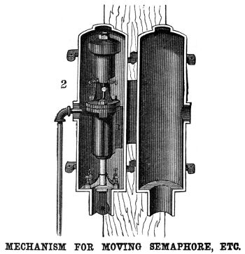 The semaphores, whose construction
is seen in the cut upon this page, are connected with a counterpoise,
so that when left to themselves the counterpoise drops and sets
them in the "Danger" position, or at right angles to
the sustaining post. Directly below each semaphore a pneumatic
cylinder, with single-acting piston, Fig. 2, is mounted, which
is connected, by means of a balance lever and connecting rod,
to the semaphore arm. As arranged, the piston, which works within
the cylinder, is pressed upward to its highest position when the
semaphore is at "Danger;" this, therefore, being the
natural position of the whole apparatus. At the top of the cylinder
a valve is arranged which can be opened electrically, and which
closes automatically by a spring. To this valve a pipe is connected
which communicates with a supply of compressed air. Above the
valve is an electro-magnet, whose armature is connected to the
valve stem. From what has been said it will be easily understood
that, if a current of electricity is sent through the magnet,
the valve will be opened. Compressed air will be admitted above
the piston, which will be depressed, and as it goes down will
force the semaphore in opposition to the counterpoise weight into
the "Safety " position. The object to be attained, therefore,
is this: When the train is on the block in advance of a set of
signals, it must automatically cut off the current of electricity
from both, so that they will both be drawn into " Danger"
position. When the train is on the next block, the current of
electricity must be again permitted to pass through the upper
semaphore magnet, forcing it into "Safety" position;
but no current must be admitted to the lower semaphore magnet
until the second block has been passed. The semaphores, whose construction
is seen in the cut upon this page, are connected with a counterpoise,
so that when left to themselves the counterpoise drops and sets
them in the "Danger" position, or at right angles to
the sustaining post. Directly below each semaphore a pneumatic
cylinder, with single-acting piston, Fig. 2, is mounted, which
is connected, by means of a balance lever and connecting rod,
to the semaphore arm. As arranged, the piston, which works within
the cylinder, is pressed upward to its highest position when the
semaphore is at "Danger;" this, therefore, being the
natural position of the whole apparatus. At the top of the cylinder
a valve is arranged which can be opened electrically, and which
closes automatically by a spring. To this valve a pipe is connected
which communicates with a supply of compressed air. Above the
valve is an electro-magnet, whose armature is connected to the
valve stem. From what has been said it will be easily understood
that, if a current of electricity is sent through the magnet,
the valve will be opened. Compressed air will be admitted above
the piston, which will be depressed, and as it goes down will
force the semaphore in opposition to the counterpoise weight into
the "Safety " position. The object to be attained, therefore,
is this: When the train is on the block in advance of a set of
signals, it must automatically cut off the current of electricity
from both, so that they will both be drawn into " Danger"
position. When the train is on the next block, the current of
electricity must be again permitted to pass through the upper
semaphore magnet, forcing it into "Safety" position;
but no current must be admitted to the lower semaphore magnet
until the second block has been passed.
Assuming, therefore, a supply of compressed air with battery
to be given, the connections are carried out on the following
basis: The rails for one block are insulated from the rails of
the preceding and following blocks. At one end the right and left
hand rails are connected by a wire containing in its circuit two
cells of gravity battery. At the other end the same rails are
connected 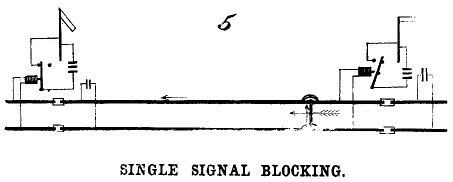 through an ordinary relay. The
battery is placed upon the end of the block first touched by the
train. As long as no train is on the block, a current will pass
through the relay, whose armature will be attracted, making a
constant contact for the current of a local battery. When a train
enters upon the track, its wheels and axles short-circuit the
battery, so that the relay is thrown out of action and the circuit
of the local battery is broken. To simplify the matter we will
assume, first, that only one set of signals, the " Home "
semaphores, are to be worked. The arrangements for this are shown
in the diagram, Fig. 5. A local battery of eight cells is arranged
in circuit with the magnet of the semaphore and with the relay,
so that when the latter is excited a current passes through the
semaphore magnet, the local battery circuit being closed by the
relay. through an ordinary relay. The
battery is placed upon the end of the block first touched by the
train. As long as no train is on the block, a current will pass
through the relay, whose armature will be attracted, making a
constant contact for the current of a local battery. When a train
enters upon the track, its wheels and axles short-circuit the
battery, so that the relay is thrown out of action and the circuit
of the local battery is broken. To simplify the matter we will
assume, first, that only one set of signals, the " Home "
semaphores, are to be worked. The arrangements for this are shown
in the diagram, Fig. 5. A local battery of eight cells is arranged
in circuit with the magnet of the semaphore and with the relay,
so that when the latter is excited a current passes through the
semaphore magnet, the local battery circuit being closed by the
relay.
When no train is on the block, it will be seen that the relay
is in action; it closes the local battery circuit. The current
from the local battery going to the semaphore magnet forces open
the valve, compressed air is admitted into the semaphore cylinder,
and the piston is driven down and the semaphore is forced into
the "Safety" position. When a train enters on the block,
the relay being thrown out of action as described, the local battery
ceases to act upon the semaphore magnet, and the semaphore is
drawn by the weight into "Danger" position.
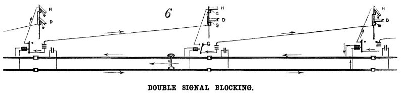
Where the "Home" and "Distant" signals
have both to be operated under the conditions described as in
use upon the railroad we are describing, a somewhat more complicated
arrangement of circuits is required, which is shown in the diagram,
Fig. 6. The line battery and relay are identical with what has
been described. The local battery circuit includes, as shown in
the diagram, within its circuit a "Distant" signal at
the commencement of one block, and the "Home" signal
at the commencement of the next block in advance. To save wire
a ground circuit is used as the return. Thus, when a block is
occupied by a train, it sets, by the action just described, the
"Distant" signal one block behind it at " Caution,"
and the "Home" signal directly behind it at " Danger"
by short-circuiting the single relay. The lower end of the piston
rod of the "Home" semaphore is provided with a circuit-closing
switch, indicated conventionally in Fig. 6, under each upper signal.
One terminal of this switch is connected to ground, the other
terminal is connected to the wire leading to the magnet of the
"Distant" signal below it. The circuit closer closes
the circuit when the piston is in the upward position or when
the "Home" semaphore is at "Danger." This
establishes a ground connection for the line leading to the "Distant"
semaphore magnet below it, which connection is of zero resistance.
This operates as a shunt to the "Distant" semaphore
magnet, so as to throw it out of action. It will be remembered
that when a magnet is out of action its semaphore, is set at "Danger."
Therefore when a "Home" signal is set at "Danger"
by the passage of a train, the "Distant" signal below
it is set at "Caution" by this action of the circuit-closing
switch, and the "Distant" signal one block in its rear
is also set at " Caution," because it is in circuit
with the "Home" signal magnet in question.
It is obvious that where electricity and compressed air are
depended on as the agents for the working of an automatic system,
failures in their action are to be anticipated. In the present
system, should electricity or pneumatic action fail, the signals
affected would at once rise to the "Danger" position.
It is here that its peculiar safety appears. The signals are only
maintained at safety by the perfect working of the apparatus.
The instant anything happens, the semaphores disclose it to the
runner of the first train passing, by the signals assuming the
"Danger" position.
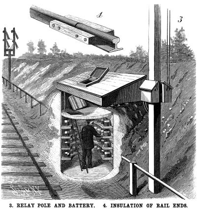 As regards the details of its
installation, the batteries are established in underground structures,
a sectional view of one of which we show in the cut, Fig. 3. The
same cut shows the relay pole, upon which the relay boxes are
placed. In order to supply compressed air, a plant of compressors
is established which communicates by pipes with a series of reservoirs
placed along the line at the foot of tire signal poles, and pipes
are carried from these to tire semaphore signals. The ordinary
sleepers are found to give sufficient insulation to the rails;
the fish plates, however, do not form adequate connection between
tire rails, so that iron wire is fastened by iron pins driven
into the foot of the rails across each joint of a block. Between
the blocks the rail ends are insulated as shown in Fig. 4. For
ground or return circuit, the pneumatic air pipes are used. For
night work powerful white lanterns are arranged on the uprights,
which, in the danger position of the signals, are masked by colored
glass carried by the rear end of the semaphore. For the "Home"
signal the glass is red, for the "Distant" signal it
is green. The same colors are used to paint the sides of the semaphore
board nearest the advancing engine. The other sides are painted
white. As regards the details of its
installation, the batteries are established in underground structures,
a sectional view of one of which we show in the cut, Fig. 3. The
same cut shows the relay pole, upon which the relay boxes are
placed. In order to supply compressed air, a plant of compressors
is established which communicates by pipes with a series of reservoirs
placed along the line at the foot of tire signal poles, and pipes
are carried from these to tire semaphore signals. The ordinary
sleepers are found to give sufficient insulation to the rails;
the fish plates, however, do not form adequate connection between
tire rails, so that iron wire is fastened by iron pins driven
into the foot of the rails across each joint of a block. Between
the blocks the rail ends are insulated as shown in Fig. 4. For
ground or return circuit, the pneumatic air pipes are used. For
night work powerful white lanterns are arranged on the uprights,
which, in the danger position of the signals, are masked by colored
glass carried by the rear end of the semaphore. For the "Home"
signal the glass is red, for the "Distant" signal it
is green. The same colors are used to paint the sides of the semaphore
board nearest the advancing engine. The other sides are painted
white.
Enough has been shown to indicate the possibilities of the
pneumatic system. It is applied also to moving switches, and a
full interlocking switch and signal system utilizing electricity,
hydraulic and pneumatic pressure, is now in use in track yards,
which plant is installed by the same company. This system we shall
probably illustrate in our next issue.
Safety Devices
| Contents Page
|


