THE MANUFACTURE OF PINTSCH GAS
Scientific American—July 9, 1898
History tells us that the first recorded instance of the lighting
of railway cars occurred on a train line, owned by the Stockton
and Darlington Company, which ran between Darlington and Sheldon,
England. The company boasted of a single coach, built 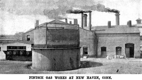 by
the great Stephenson in the year 1825, which was drawn by a single
horse over iron rails between the places named. The " Experiment,"
as this forerunner of the Pullman vestibule was called, was a
very modest and somewhat uncouth machine, which resembled—so
says the historian—the caravans which were yet to be seen
at county fairs containing the great " Giant and Dwarf "
and other wonders of the world. A row of seats ran along each
side, and a long table was fixed in the center, access being had
by a door at the back end. It seems that to one Thomas Dixon,
the driver of the " Experiment." belongs the credit
of being the inventor of car lighting on the rail; for on dark
winter nights, having compassion on the passengers, he would buy
a penny candle and place it lighted among them on the rough board
which answered the purpose of a table. by
the great Stephenson in the year 1825, which was drawn by a single
horse over iron rails between the places named. The " Experiment,"
as this forerunner of the Pullman vestibule was called, was a
very modest and somewhat uncouth machine, which resembled—so
says the historian—the caravans which were yet to be seen
at county fairs containing the great " Giant and Dwarf "
and other wonders of the world. A row of seats ran along each
side, and a long table was fixed in the center, access being had
by a door at the back end. It seems that to one Thomas Dixon,
the driver of the " Experiment." belongs the credit
of being the inventor of car lighting on the rail; for on dark
winter nights, having compassion on the passengers, he would buy
a penny candle and place it lighted among them on the rough board
which answered the purpose of a table.
From the sputtering candle which made darkness visible on the
"Experiment" to the brilliant Pintsch gas light of a
luxurious 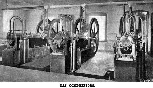 modern railroad car is a far
cry; and if space permitted, it would furnish an interesting story
to follow the growth of car lighting through the intervening three-quarters
of a century. Confining ourselves to the present subject, however,
we must be content to state that Pintsch gas is so named after
its inventor, Julius Pintsch, of Berlin, who, realizing the urgent
necessity for a better method of lighting than by the oil lamp
or the tallow candle, which was even in his day in use in some
parts of Europe, invented his justly famous system of car lighting
by gas. Briefly stated, Pintsch gas is a fixed gas manufactured
from naphtha, which, after being thoroughly purified, is compressed
into storage tanks, and from them drawn off through an automatic
regulator, which reduces it to the pressure of one-third of an
ounce per square inch, at which it is used at the burners. modern railroad car is a far
cry; and if space permitted, it would furnish an interesting story
to follow the growth of car lighting through the intervening three-quarters
of a century. Confining ourselves to the present subject, however,
we must be content to state that Pintsch gas is so named after
its inventor, Julius Pintsch, of Berlin, who, realizing the urgent
necessity for a better method of lighting than by the oil lamp
or the tallow candle, which was even in his day in use in some
parts of Europe, invented his justly famous system of car lighting
by gas. Briefly stated, Pintsch gas is a fixed gas manufactured
from naphtha, which, after being thoroughly purified, is compressed
into storage tanks, and from them drawn off through an automatic
regulator, which reduces it to the pressure of one-third of an
ounce per square inch, at which it is used at the burners.
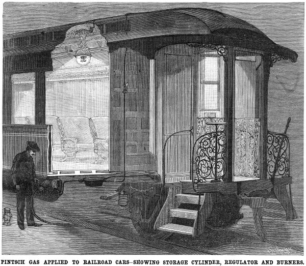
The gas was designed specially for the illumination of railroad
cars; and while it has found a useful field in other directions,
notably in the illumination of buoys and beacons, where its capacity
for storage and its ability to stand rough usage without going
out, render it extremely valuable, it is in car lighting that
it has found, and is ever likely to find, its most successful
application.
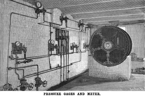
We present in this issue illustrations of a typical Pintsch
gaslight plant as installed at New Haven, Conn., for supplying
the cars of the New York, New Haven and Hartford Railroad. The
plant consists of retorts for the distillation of the oil, purifiers,
compressors, storage tanks and gas mains to lead the gas to the
station platforms at which the storage tanks on the cars are charged.
It should be explained that the general view of the plant varies
in minor details from the plant as it actually exists, the relative
position of the various parts having been rearranged somewhat,
and the number of parts reduced, so as to place each step of the
process clearly before the reader.
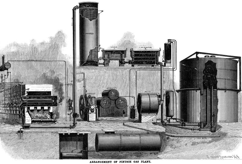
The oil from which the gas is made is known as "distillate,"
and is purer than the commercial naphtha. It is brought to the
works on the company's cars in casks, and is run by gravity into
three cylindrical storage tanks, whose combined capacity is 14,000
gallons. From these the oil runs through a pipe, which is provided
with a check-valve, into a small cylindrical tank from which it
is raised by pneumatic pressure to another tank of about 50 gallons
capacity, located above the retorts. When the lower tank is full,
the Westinghouse air pump is started, and the air, which is led
in above the liquid, forces the latter out through the pipe which
will be noticed leading from the bottom of the tank, and up to
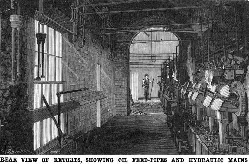
the tank above the retorts. The retorts are arranged in sets of
four, two upper and two lower, with a fire below each set, and
there are eight fires in all. The cast iron retorts are about
10 inches in diameter, with a 1½-inch shell. Each retort
is connected with the one above it by a double bonnet at the front
end. The rear end of the upper retort is closed by a cover through
which the oil is led by means of a small pipe. The lower retort
leads into the "hydraulic main," by which the products
of distillation are carried away for further treatment. The covers
are taken off when it becomes necessary to clean the retorts and
remove the deposits which gather on the inside of the shell. If
the deposit is soft, it is cut away with a chisel bar, but if
it is hard, it is burnt off by admitting a draught of air or by
allowing a jet or steam to play upon it. The joints are sealed
hermetically with lime to prevent the escape of the gas.
 From the 50-gallon tank the oil
is led by a small pipe into the upper retort, and spreads in a
thin layer over a sheet iron tray, where it is vaporized by the
heat of the furnace. The gas is prevented from returning by placing
a suitable trap in the oil feed-pipe, and the flow of the oil
is regulated by means of a micrometer screw which permits of varying
the supply according to the temperature. The distillation of the
oil which commences in the upper retort is completed in the lower
one, where the heat is greatest. The gas passes from the retorts
to a stand-pipe, which terminates in a sealing cistern of water
at the bottom of the hydraulic main, the latter serving to prevent
the escape of gas. The water is kept in constant circulation,
being fed by a water pipe which runs above the retorts, and flowing
out into the "tar trap" together with the gas and a
small amount of tar which has been condensed in the cistern. The
tar trap is a square iron box in which much of the tar, together
with the overflow water from the cistern, is collected. From this
the tar and water flow by gravity into a seal pot, which is shown
in the illustration, sunk in the ground to the left of the tar
trap. This is simply a cylindrical vessel filled with water, the
pipe from the tar pot being carried down and opening into the
vessel near the bottom. The arrangement seals the apparatus against
the passage of the gas, while at the same time allowing the liquids
to pass away. From the 50-gallon tank the oil
is led by a small pipe into the upper retort, and spreads in a
thin layer over a sheet iron tray, where it is vaporized by the
heat of the furnace. The gas is prevented from returning by placing
a suitable trap in the oil feed-pipe, and the flow of the oil
is regulated by means of a micrometer screw which permits of varying
the supply according to the temperature. The distillation of the
oil which commences in the upper retort is completed in the lower
one, where the heat is greatest. The gas passes from the retorts
to a stand-pipe, which terminates in a sealing cistern of water
at the bottom of the hydraulic main, the latter serving to prevent
the escape of gas. The water is kept in constant circulation,
being fed by a water pipe which runs above the retorts, and flowing
out into the "tar trap" together with the gas and a
small amount of tar which has been condensed in the cistern. The
tar trap is a square iron box in which much of the tar, together
with the overflow water from the cistern, is collected. From this
the tar and water flow by gravity into a seal pot, which is shown
in the illustration, sunk in the ground to the left of the tar
trap. This is simply a cylindrical vessel filled with water, the
pipe from the tar pot being carried down and opening into the
vessel near the bottom. The arrangement seals the apparatus against
the passage of the gas, while at the same time allowing the liquids
to pass away.
 An 8-inch pipe conducts the gas
to a large condenser, located on the floor above. This is similar
in construction to an ordinary tubular boiler. It has a chamber
at each end, connected by a number of 3-inch tubes, around which
cold water is kept constantly circulating. As the gas travels
through the tubes it is cooled, and the moisture, together with
the remainder of the tar, is condensed, collecting in the lower
chamber, from which it drains into a drip-pot located on the lower
floor. From the condenser the gas passes into the washer. It enters
through a vertical 6-inch pipe, the top of which is covered by
a hood, which dips one inch below the surface of the water and
below a horizontal perforated screen. The gas is thus caused to
pass through the water in innumerable fine streams, with the result
that it is freed from impurities, which consist chiefly of the
heavy and ungasified portions of the oil, that are not removed
by cooling and are carried thus far in the process. The gas is
next led to the purifier, a rectangular iron box containing a
number of perforated trays, on which is spread a layer of wood
chips and shavings covered with slaked lime. The shavings are
placed there to keep the lime loose and prevent its packing down
upon the trays. The gas enters at the bottom and, in passing up
through the lime, it is relieved of its sulphur. It is then led
through a meter capable of registering 100,000,000 cubic feet,
and it finally enters the gasometer. Both the inlet and outlet
pipes of the gasometer are provided with "drips" to
catch the moisture that may be precipitated. An 8-inch pipe conducts the gas
to a large condenser, located on the floor above. This is similar
in construction to an ordinary tubular boiler. It has a chamber
at each end, connected by a number of 3-inch tubes, around which
cold water is kept constantly circulating. As the gas travels
through the tubes it is cooled, and the moisture, together with
the remainder of the tar, is condensed, collecting in the lower
chamber, from which it drains into a drip-pot located on the lower
floor. From the condenser the gas passes into the washer. It enters
through a vertical 6-inch pipe, the top of which is covered by
a hood, which dips one inch below the surface of the water and
below a horizontal perforated screen. The gas is thus caused to
pass through the water in innumerable fine streams, with the result
that it is freed from impurities, which consist chiefly of the
heavy and ungasified portions of the oil, that are not removed
by cooling and are carried thus far in the process. The gas is
next led to the purifier, a rectangular iron box containing a
number of perforated trays, on which is spread a layer of wood
chips and shavings covered with slaked lime. The shavings are
placed there to keep the lime loose and prevent its packing down
upon the trays. The gas enters at the bottom and, in passing up
through the lime, it is relieved of its sulphur. It is then led
through a meter capable of registering 100,000,000 cubic feet,
and it finally enters the gasometer. Both the inlet and outlet
pipes of the gasometer are provided with "drips" to
catch the moisture that may be precipitated.
From the gasometer the gas is drawn by a 2-inch pipe through
the "freezer," a plain cylindrical vessel, to the compressors.
The freezer is connected directly with the suction of the compressors,
and the rarefaction of the gas, by further lowering its temperature,
condenses the moisture and dries the gas; hence the freezer is
also known as the drier. The compression is done by the three
single-stage compressors shown in the illustration. It will, be
noticed that connection is made from the compressors to both the
inlet and outlet of the gas tank. This is done to provide for
any emergency, such as the failure or repair of the tank, in case
of which the gas could be drawn direct from the meter.
 The gas is compressed to 14 atmospheres
and stored in a stack of accumulators—steel cylinders, 20
feet in length, from which it is drawn off for use as required.
Before entering the accumulators, however, the gas passes through
a hydrocarbon tank, in the bottom of which the hydrocarbon is
deposited. A certain amount of hydrocarbon is also deposited at
the bottom of the accumulators, and a series of small three-eighth-inch
pipes lead from there and from the bottom of the hydrocarbon tank
to a storage tank on the upper floor, to which the hydrocarbon
is forced by the pressure of the gas. The gas is compressed to 14 atmospheres
and stored in a stack of accumulators—steel cylinders, 20
feet in length, from which it is drawn off for use as required.
Before entering the accumulators, however, the gas passes through
a hydrocarbon tank, in the bottom of which the hydrocarbon is
deposited. A certain amount of hydrocarbon is also deposited at
the bottom of the accumulators, and a series of small three-eighth-inch
pipes lead from there and from the bottom of the hydrocarbon tank
to a storage tank on the upper floor, to which the hydrocarbon
is forced by the pressure of the gas.
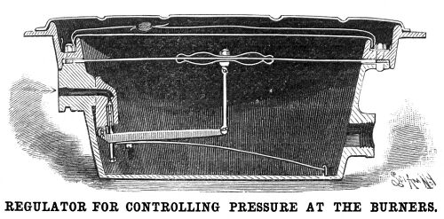
The gas is conducted from the accumulators by three 2-inch
mains to the platforms of the New Haven station, where there are
33 filling valves, each of which is provided with 35 feet of hose
and the necessary couplings to connect with the storage cylinders
underneath the cars. The gas in these cylinders is under a pressure
of 10 to 12 atmospheres, and before it can be used at the burners
the pressure has to be reduced to about an ounce. This is accomplished
by passing it through a regulator placed beneath the car. The
details of the regulator are shown in the accompanying sectional
view. The gas enters, as indicated by the arrow, by a small valve,
the stem of which acts upon a lever controlled by the pressure
of a steel spring. The top of the receiver is closed by a flexible
airtight leather diaphragm which is connected by a vertical rod
to the long arm of the lever just mentioned. When the gas exceeds
a certain pressure, it lifts the diaphragm, thereby raising the
lever and closing the inlet valve. From the regulator the gas
passes to the burners at the roof of the car, where it is controlled
in the usual manner.
When it is compressed the oil gas possesses an illuminating
power six times greater than that of city gas. The value of the
gas for the special purposes to which it is put consists mainly
in the fact that, while coal gas loses the greater part of its
illuminating power by compression, oil gas loses only one-eighth.
It is this quality that renders the Pintsch gas eminently adapted
for car lighting and for use in buoys and beacons, or where it
is subject to unusually rough usage.
Various Apparatus
| Contents Page
|


