|
1087
CURVED TRACK.
1664. Difference in Length of Inner and Outer Rails of a
Curve.—It is evident that the radius of the outer
rail of a curve is greater than that of the inner rail, and, consequently,
its length is greater. This difference may be taken at 1 and one-thirty-second
inches per degree of curve per 100 feet, for standard gauge track.
The difference in length between the inner and the outer rails
of a curve may be found by any of the three following rules:
Rule 1.—Multiply the degree of the curve by
the length in stations of 100 feet, and this product by 1and one-thiryty-second
inches. The result will be the difference in length between the
inner and outer rails in inches.
EXAMPLE.—The degree of a curve is 4
degrees; its length 520 feet; what is the difference in length
between the inner and outer rails of the curve?
SOLUTION—520 feet = 5.2 stations of 100 feet each. 4 x
5.2 = 20.8. 1 and one-thirty-second = 1.03125 in. 20.8 x 1.03125
= 21.45in. = 1.7875ft.
Rule 2.—Multiply the distance between the center
lines of the rails by the length of the curve in feet and divide
the product by the radius of the track curve.
EXAMPLE.—A 4 degree curve is 520 feet
in length; the distance between the center lines of the rails
is 4 ft. 10½ in.; what is the difference in length between
the inner and outer rails of the curve?
SOLUTION.—The radius of a 4 degree curve is 1432.69 ft.
(See table of Radii and Deflections.)
10½ in. reduced to the decimal of a foot is
.875 4.875 x 520 divided by 1,432.69 = 1.77 ft.
Rule 3.—Multiply the excess for a whole
circumference by the total number of degrees in the curve, and
divide the product by 360. The excess of a whole circumference,
no matter what the degree of curve, is equal to twice the distance
between rail centers multiplied by 3.1416.
EXAMPLE.—A 4 degree curve is 520 feet
in length; the distance from center to center of the rails is
4 ft. 10½ in. ; what is the difference in length between
the inner and outer rails of the curve?
SOLUTION.—The distance between rail centers is 4.875 ft.
4.875 x 2 x 3.1416 = 30.6306 ft. A 4 degree curve for 520 ft.
contains 20.8 degrees. 30.6306 x 20.8 divided by 360 = 1.77 ft.
1088
For light curves laid to exact gauge, the first rule is the
simpler one, but for short curves where the gauge is widened use
either the second or the third method.
These rules should be applied in determining the number of
short rails for curves, when loading material at the supply yard
for forwarding to the track-layers. As previously stated, a safe
rule is one 29½-foot rail per 100 feet for each 6 degrees
of curvature. In laying track with either even or, broken joints,
the required number of short rails must be laid in proper order
if a first-class job is to be expected.
1665. Curving Rails.—When laying track on
curves, in order to have a smooth line, the rails themselves must
conform to the curve of the center line. To accomplish this the
rails must be curved. The curving should be done with a rail bender
(see Fig. 495)
or with a lever, as shown in Fig.
497. The rail bender is preferable.
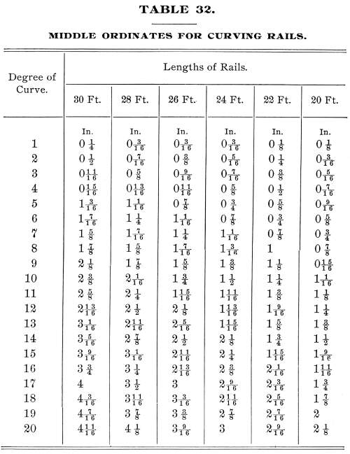
To guide those in charge of this work, a table of middle and
quarter ordinates for a 30-foot rail for all degrees of curve
should be prepared.
The accompanying table of middle ordinates for curving rails
is calculated by using the formula
m = c (squared) divided by 8 R' (112.)
in which m is the middle ordinate; c, the chord,
assumed to be of the same length as the rail, and R, the
radius of the curve.
EXAMPLE.—What is the middle ordinate
m of a 30-foot rail for an 8 degree curve?
SOLUTION.—The radius of an 8 degree curve is 716.78 ft.
Applying the formula, we have
m = 30 (squared) divided by 8 x 716.78 = 900 divided
by 5,734.24 = 0.157 ft = 1 and seven-eighths ins.
The results obtained from this formula are not theoretically
correct, yet the error is so small that it may be ignored in practical
work. With a table of radii such as is given in the table of Radii
and Chord and Tangent Deflections, a table of ordinates may be
readily calculated by substituting the known values in formula
112.
1089
In curving rails, the ordinate is measured by stretching a
cord from end to end of the rail against the gauge side, as shown
in Fig.517.
Suppose the rail A B is 30 feet in length, and the curve
8 degrees. Then, by the previous problem, the middle ordinate
at a should be 1 and seven-eighths inches. To insure a
uniform curve to the rails, the ordinates at the quarters b
and b' should be tested. In all cases the quarter ordinates
should
1090
be three-quarters of the middle ordinate. In Fig.
517, if the rail has been properly curved, the quarter ordinates
at b and b' will be ¾ x 1 and seven-eighths in. = 1 and
thirteen-thirty-seconds, say 1 and three-eighths in.
With practice, a man having a good eye and good judgment will
soon find his eye measurements closely checking his table measurements.
When a quantity of rails are to be curved for curves of different
degrees, it is a good plan to mark the degree of the curve of
each rail in white paint on the web of the rail on the concave
side. There should be ample force to handle the rails with dispatch,
else much time will be wasted. The use of sledges in curving rails
should under no circumstances be allowed. There is great danger
of fracture, and often a flaw is caused which at the time is not
perceptible, but which may, under the stresses caused by frost
and heavy trains at high speed, result in a broken rail, with
serious consequences.
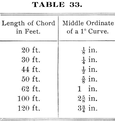
In track work it is often necessary to ascertain the degree
of a curve, though no transit is available for measuring it. The
following table contains the middle ordinates of a one degree
curve for chords of various lengths:
1091
The lengths of the chords are varied so that a longer or shorter
chord may be used, according as the curve is regular or not.
The table is applied as follows: Suppose the middle ordinate
of a 44-foot chord is 3 inches. We find in the table that the
middle ordinate of a 44-foot chord of a one-degree curve is ½
inch. Hence, the degree of the given curve is equal to the quotient
of 3 divided by ½ = 6 degree curve.
Additional examples are given as follows:
1. The middle ordinate of a 100-foot chord is 14¾
inches; what is the degree of the curve?
Ans. 5.6 degrees, nearly.
The degree of the curve is probably 5 degrees 30 minutes.
2. The middle ordinate of a 50-foot chord is 5¼
inches; what is the degree of the curve?
Ans. 8.4 degrees.
The degree of the curve is probably 8 degrees 30 minutes.
3. Calculate by rule 1 the difference in lengths
between the inner and the outer rails of a 7 degree curve 475
feet in length.
Ans. 34.29 in. = 2.857 ft.
4. Solve Example 3 by rule 2.
Ans. 2.827 ft.
1666. Springing Rails into Curve.—Rails should
never be sprung and spiked to a curve; the elastic force of the
steel is constantly acting, and is sure to force the track out
of line. Each passing train, through its centrifugal force, aids
the rails to regain their original form. The result is that in
a short time the curve, especially it a sharp one, wilt show an
angle at each joint. The effect at these angles is to cause a
sudden lurch of the car at each joint, causing not only discomfort
to passengers, but serious and constant wear and strain upon the
rolling stock.
1667. Widening Gauge of Curves.—In passing over
curved track, the car wheels bind hard against the outside rail
at the curve. The reason for this is that the difference between
the gauge of the track and the gauge of the wheels is taken up
by the wheel base, which forms a chord to the curve of the track,
instead of being parallel to the rails, as is the case on a straight
line. To lessen this friction,
1092
the gauge is usually widened on curves to the amount of one-sixteenth
inch per degree, but never to exceed 1 inch on any curve. The
increase in gauge is usually made in quarter-inches, that being
the amount allowed for 4 degrees. The necessity for widening the
gauge on sharp curves is still more apparent when we consider
that provision must be made to accommodate cars of both standard
gauge (4 feet 8½ inches) and for those of 4 feet 9 inches
gauge, common to Southern roads.
When the gauge is not widened, a wide-gauged car is liable
to mount the rail, especially if the flanges of the wheels are
badly worn and sharp. The effect of all curvature is to increase
the train resistance, and on sharp curves, this resistance, due
to friction, becomes so great as to largely reduce the train load.
All train loads are limited by the maximum resistance which they
must overcome. This maximum resistance may be concentrated upon
a single curve, and it is at once apparent that a railroad company
might well incur heavy expense in reducing this curvature, if
by so doing they could add one extra car to each train load. Another
charge against curvature is the loss of time to passenger trains
which can not run over sharp curves, except at reduced speed.
All curves exceeding eight degrees, besides their resistance to
trains, cause a direct loss of time to all fast passenger trains.
1668. Guard Rails on Short Curves.—On straight
track, laid to exact gauge, the guard rail is spaced 1 and seven-eighths
inches from the gauge rail; but when the gauge is widened, as
on sharp curves, the amount of the increase in gauge must be added
to the space between the gauge and the guard rail.
1669. Lining Curves.—A common habit of trackmen
when lining curves is to throw the curve outwards to line. The
effect of this, in time, is to reduce the degree of curvature
at the ends of the curve and sharpen it at the center, besides
crowding the roadway on the outside of the curve.
1093
A safe rule is to always throw the track inwards, i.e.,
towards the center of the curve. It is at once apparent that the
effect of the centrifugal force of the train in passing over a
curve is to throw the track outwards, and in lining curves, the
track should be thrown inwards, if for no other purpose than to
overcome this effect of the trains. The effect of throwing the
track outwards when lining a curve is shown in Fig. 518, in which A B C represents
the true line of the curve and A E C the position of the
tracks due to improper lining.
When track is first laid, there should be a track center stake
driven at every 50 feet and carefully centered with a tack. Before
and after ballasting, the track should be carefully lined to the
center stakes, and if the rails have been properly curved the
track will hold its line, with occasional retouching, for years.
In the case of a badly lined curve, select a piece of track
60 feet in length, which appears to be in good line. There are
few curves, however badly out of line, but will show at least
60 feet of good line. At each end of the 60 feet of good track
set an accurate center stake, and one in the center of the track
midway between them. In Fig.
519, A and B represent the center stakes 60
feet apart, and C the stake midway between them. Stretch
a cord from A to B, and measure the distance from
L, its middle point, to C. The distance C L is
the middle ordinate of a 60-foot chord. Next, mark the middle
point L of the chord, and move the end A of the
chord to C. Measure from B the
1094
distance B M = C L, and carry the measuring cord forwards,
stretching it taut, and in the line C M, as determined
by the offset B M. The forward end D of the cord
will mark the spot for another track center. Then, move ahead
as before, measuring another offset and stretching the cord to
locate another center stake at E, In this way a perfect
curve may be run in without the use of an instrument. It is better
policy to set the track centers in line with the faces of the
stakes for line rather than the tack centers, as the cord is sure
to line properly to the faces of the stakes, but in order to line
their centers they must be practically of the same height, which
is sometimes difficult to obtain, especially if the ballast contains
stone.
Having set all the track centers, select a track gauge which
is square and true, and mark a point midway between the gauge
lines. Then, place the gauge on the track close to the track center,
and direct the men to move the track until the middle point of
the track gauge coincides with the track center. Line up the track
at each track center until the entire curve has been moved to
line; then, repeat the operation, giving the final touches, as
a second lining should be sufficient.
1670. Elevation of Curves.—To counteract the centrifugal
force which is developed when a car passes around a curve, the
outer rail is elevated. The amount of elevation will depend upon
the radius of the curve and the speed at
1095
which trains are to be run. There is, however, a limit in track
elevation, as there is a limit in widening gauge, beyond which
it is not safe to pass.
When we consider that the centrifugal force of a car increases
as the degree of curvature, and as the square of the
speed, we readily see how a slight decrease in speed will
equalize a great increase in curvature.
To illustrate: A car passing around an 8-degree curve will
have double the centrifugal force of a car passing around a 4
degree curve at the same speed. But to neutralize the effect of
sharpening the curve from 4 to 8 degrees, it is not necessary
to halve the speed, but only to reduce it in an inverse proportion
to the square root of the degrees of curvature. Thus, if a speed
of 60 miles per hour is admissible on a 4-degree curve, the speed
on an 8-degree curve is obtained by the proportion 60:
If we again double the degree of the curve to 16 degrees, we
only reduce the admissible speed of equal safety to 30 miles per
hour. Hence, it will be seen that the centrifugal force developed
by an increase in speed is not proportional to the centrifugal
force developed by an increase in curvature. In consequence of
this varying relation between curvature and speed, no fixed rule
can be followed for elevating the outer rail of curves.
It is a safe rule to elevate all curves to suit the highest
speed of trains passing over that part of the track. Ordinarily
freight trains require the same track elevation as passenger trains.
All railroad men know that freight trains repeatedly run at passenger
train speed. The aim of every freight train conductor is to "make
time," and he makes it whenever the grades and train loads
permit.
On rolling grades it is often necessary to run down a grade
at top speed in order to acquire sufficient momentum to carry
the train to the summit of the following grade. Every day fast
running is necessary in order to make up for time lost through
unavoidable delays; hence, if a curved track is elevated to meet
the requirements of passenger trains, freight trains will be equally
well served. All curves, when possible,
1096
should have an elevated approach on the straight main track,
of such length that trains may pass on and off the curve without
any sudden or disagreeable lurch. The length of the approach should
be in proportion to the elevation of the curve and not to its
degree.
A good rule for curve approaches is the following: For each
half-inch or fraction thereof of curve elevation, add 30 feet
or 1 rail length to the approach; that is, if a curve has an elevation
of 2 inches, the approach will have as many rail lengths as ½
is contained in 2, which is 4 times. The approach will, therefore,
have a length of 4 rails of 30 feet each, or 120 feet.
The following formula by Searles, viz.,
c = 1.587 V, (113.)
gives the length of the chord c, whose middle ordinate
is equal to the proper elevation of the outer rail
of the curve for any velocity V in miles per hour.
EXAMPLE.—The curve is 8 degrees, and
the velocity 40 miles pet hour; what is the proper elevation for
the outer rail of the curve?
SOLUTION. -Substituting the given values in formula 113,
c = 1.587 V,
we have c = 1.587 x 40 = 63.48 feet, the length of the
required chord.
To find the middle ordinate of this chord, we apply formula
112.
We have just found c = 63.48 feet, and R = the
radius of an 8 degree curve = 716.78 feet.
Substituting these values of c and R in the above
formula, we have
m = 63.48 (squared) divided by 8 x 716.78 = 4,029.7
divided by 5,734.2 = .71 ft., nearly = 8½ in.
This result is too great. The best authorities on this subject
place the maximum elevation at one-seventh the gauge, or about
8 inches for standard gauge of 4 feet 8½ inches. The gauge
on a 10 degree curve elevated for a speed of 40 miles an hour
should be widened to 4 feet 9¼ inches.
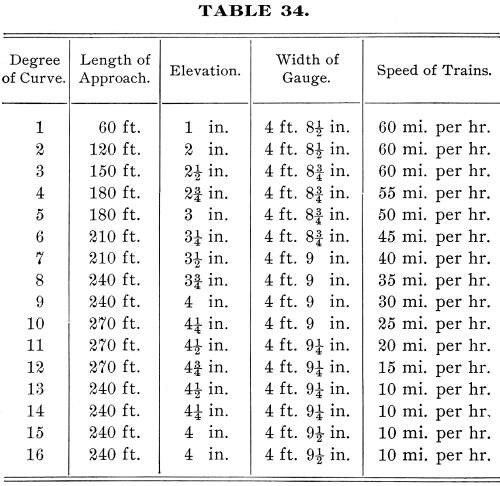
The following table for elevation of curves is a compromise
between the extremes recommended by different engineers. It is
a striking fact that experienced trackmen never elevate track
above 6 inches, and many of them place the limit at 5 inches:
1097
Many persons overrate the objections to sharp curves, especially
where the grades are low. Their great objection is not in their
being an obstacle to high speed, but in their great resistance
to traction. Freight trains, which are usually heavily loaded,
are much more impeded by sharp curves than passenger trains, which
are generally lighter and made up of cars which more readily adjust
themselves to irregularities in line and surface.
No curve exceeding 10 degrees should be placed in the main
line of any railroad. The additional cost of operating and maintaining
a sharper curve would pay for the additional outlay necessary
to bring the degree within the 10-degree standard. Many roads
place the maximum curve at 6 degrees, and though beyond the reach
of many roads, it is a safe standard.
1098
Besides the loss of time necessitated by running slowly on
short curves, there is a much greater loss due to the wear and
tear on rolling stock and upon the rails themselves. The friction
of the wheel flanges against the rails rapidly wears them out,
and the continual lurching and rolling of the cars detract greatly
from the comfort of passengers.
Most of the trunk lines in the United States have been greatly
improved since their first construction, especially in their alinement,
some of them being practically rebuilt. The Pennsylvania R.R.
between Philadelphia and Harrisburg is a striking instance of
the great improvement, both in alinement and grade, of a line
originally cheaply and poorly built. Many of the original curves
have been removed, and all of them lightened. In many places the
original line has been entirely abandoned, and a new and better
one adopted. This road is, however, an exceptional case, as few
lines in the world could afford to make slight changes involving
so great cost.
1671. The Elevation of Turnout Curves.—The speed
of all trains in passing over turnout curves and
crossovers is greatly reduced, so that an elevation of ¼
inch per degree is amply sufficient for all curves under 16 degrees.
On curves exceeding 16 degrees, the elevation may be held at 4
inches until 20 degrees is reached, and on curves exceeding 20
degrees, three-sixteenths of an inch of elevation per degree may
be allowed until the total elevation amounts to 5 inches, which
is sufficient for the shortest curves.
1672. Curve Approaches Between Reverse Curves.—If
possible, there should be a level piece of track, at least 60
feet in length, between reverse curves, besides the elevated approaches
to the curves. When the whole of the intermediate tangent is required
in making the elevated approaches to the curves, commence at the
middle of the intermediate tangent, if both curves are of the
same degree. If, however, they are of different degrees, make
the approach to each curve in proportion to its degree. In elevating
the approaches to the curves, give to the first rail
1099
length an elevation of inch, after which give ½ inch
additional elevation per rail length, or, if necessary, 1 inch
additional elevation, so as to make the total elevation of the
approach equal to the elevation of the outer rail of the curve.
When a curve is compounded, commence to increase or decrease
the elevation far enough back from the point of compound curvature
to give to the second branch of the compound curve the elevation
which it requires. This increase or decrease in elevation is made
at the rate of ½-inch per rail length, precisely as in
elevating the approach to a regular curve. When the changes in
a compound curve are frequent and abrupt, it is best to elevate
the outer rail for the highest degree of the curve and carry this
elevation uniformly throughout the curve.
1673. Putting the Elevation in Curves.—If the track
is in good surface, first catch up all the low joints on the inner
rail of the curve. The elevation of the outer rail is determined
by means of the track level shown in Fig. 520. For leveling track, the edge
a b of the track level is placed upon the rails, and when
perfectly level the bubble c of the spirit level will rest
in the middle of the tube. The steps d, e, etc., of the
track level are made 1 inch in height, so that when the step d
is placed on the outer rail of a curve and the rail raised until
the bubble of the spirit level rests in the middle of the tube,
the outer rail has an elevation of 1 inch. Similarly, the step
e, when brought to a level, would indicate a track elevation
of 2 inches, etc.
Having determined the amount of elevation required for the
curve, the outer rail is raised with the track jack and the ballast
thoroughly tamped under the ties. The elevation
1100
should be about ½ inch in excess of that required, in
order that provision may be made for settlement.
In dressing the track after the elevation has been made, make
the crown of the ballast at not more than one-third of the width
of the gauge from the outer rail, in order to secure drainage.
The raising of the outer rail reduces the outer slope and increases
the inner slope of the ballast. If the curve is sharp, the ballast
on the outer half of the track is practically level and holds
water, instead of shedding it. By crowning the ballast as directed,
thorough drainage is insured.
1674. The Effects of Curved Track upon Locomotive and Car
Wheels.—The effect of all curved track, however easy
the curve, is to wear the flanges and treads of car wheels. This
effect is due to the centrifugal force which forces the flanges
of the wheels against the head of the outside rail of the curve.
The elevation of the outer rail, the widening of the gauge,
and the coning of the car wheels, all combine to reduce this friction
and consequent wear.
Where the elevation is insufficient, the friction increases,
and if the gauge is the same as on straight track, there is great
danger of the wheels mounting the rails, especially if the flanges
are badly worn. The conclusion from many years of experiment and
close observation is that the wear of rails on curved track is
largely due to the driving wheels of the engine. When the tires
become worn, the wear of the rails rapidly increases, and hence
the importance of careful and repeated inspection of the driving
wheels. As soon as they show considerable wear, the tires should
be turned off to true lines. Besides preventing unnecessary wear
of rails, this greatly increases the tractive power of the engine.
When the treads of car wheels become badly worn, especially at
the flanges, there is bound to be more or less slipping of the
wheels. For the outer rail, being the circumference of a greater
circle, should require a wheel of greater diameter than the inner
wheel, if both are to make
1101
the same number of revolutions. This increased diameter is given
by the coning of the wheels, shown in Fig. 521, in which the rail a is
on the outside of the curve. An inspection of the figure will
show that the cone-shaped tread of the wheel b gives a
greater diameter to the wheel at c d than at e f.
In passing around the curve, the flange of the wheel b is
forced against the rail a, while the flange of the wheel
h recedes from the rail g. This increases the diameter
of the wheel b, while decreasing that of the wheel h,
and so the excess in length of the outer rail of the curve is
at least partially covered.
Careful experiment proves that under the most favoring conditions
some slipping of the wheels is bound to occur. The friction
between wheels and rails rapidly increases as the rails become
worn, and, as soon as the head of the outer rail of a curve becomes
badly worn, the outer rail should be taken up and placed on the
inside of the curve, and the inner rail put in its place. This
furnishes almost new wearing surfaces to the wheel, and the life
of the rails is greatly prolonged.
1675. Care of Curved Track.—As curved track
offers greater resistance and greater danger to passing trains
than straight track, special effort and pains should be taken
to maintain it in perfect order. All trackmen know that a low
spot on a curve will cause every car in a train to
1102
lurch heavily towards the low side. By careful watching, and
by prompt and thorough repairs, curved track may be kept in perfect
order. It is highly important that the elevation of the outer
rail be kept uniform, and no foreman, however experienced, should
place dependence upon his eye in estimating curve elevation.
Both the civil engineer and the track foreman will do well
to cultivate each other, the engineer imparting theoretical knowledge
in exchange for practical knowledge. The result will certainly
promote mutual respect and enhance the efficiency of both.
Track Page
| Contents Page
|


