|
1102
FROGS AND SWITCHES.
FROGS.
1676. Turnouts.—A turnout is a device for
enabling an engine and train to pass from one track to another.
It consists of two lines of rails a b and c d (see
Fig. 522),
so laid as to form a reversed curve uniting the two tracks A
B and C D. The several parts of a turnout are as follows:
The switch rails e f and g h, the
frog k, and the two guard-rails l m
and n o. The stationary ends c and g of the
switch rails are called the heels, and the movable ends
f and h are called the toes. The distance
f p, through which the toes f and h move,
is called the throw. The throw must equal the width of
the head of the rail, with sufficient additional width to allow
the flanges of the wheels to pass freely between the main rails
r s and t u and
1103
the turnout rails a b and c d. The throw on tracks
of standard gauge is 5 inches; that is, the toes f and
h are moved 5 inches from their original position in the
main track in forming the turnout curve on which the train is
to pass from the main track A B to the siding C D.
The movement of the switch rails is effected by means of a
lever.
1677. The Frog.—The frog is a device by
means of which the rail at the turnout curve crosses the rail
of the main track. The frog shown in Fig. 523 is made of rails having the same
cross-section as those used in the track, Its parts are as follows:
The wedge shaped part A is the tongue, of which
the extreme end a is the point. The space b,
between the ends c and d of the rails, is the
mouth, and the channel which they form at its narrowest
point e is the throat. The curved ends f and
g are the wings.
That part of the frog between A and A' is called
the heel. The width h of the frog is called its spread.
Holes are drilled in the ends of the rails c, d, k,
and l to receive the bolts used in fastening the rail splices,
so that the rails of which the frog is composed form a part of
the continuous track.
1678. The Frog Point.—The theoretical point
of frog a' (see Fig. 523) and
the actual point a are quite dissimilar. The reason for
making a the point of frog is that if the theoretical and
actual point of frog were the same, the point would be so small
that the first blow inflicted by a passing locomotive or car would
completely destroy it. The frog point is accordingly placed at
a, where its width is about ¼ of an inch.
1104
1679. The Frog Number.—The number of a frog
is the ratio of its length to its breadth, i.e., the quotient
of its length divided by its breadth.
Thus, in Fig. 523, if the length
a' 1, from point to heel of frog is 5 feet, or 60 inches,
and the breadth h of the heel is 15 inches, the number
of the frog is the quotient of 60 ÷ 15 = 4. Theoretically,
the length of the frog is the distance from a to the middle point
of a line drawn from k to 1; practically, we take
as the length the distance from a to 1. As it is
often difficult to determine the exact point a of the frog, a
more accurate method of determining the frog number is to measure
the entire length dl of the frog from mouth to heel, and divide
this length by the sum of the mouth width b and the heel width
h. The quotient will be the exact number of the frog.
For example, if in Fig. 523, the
total length d l of the frog is 7 feet 4 inches, or 88
inches, and the width h is 15 inches, and the width
b of the mouth is 7 inches, then the frog number is 88
÷ (15 + 7) = 4. Frogs are known by their numbers. That
in Fig. 523 is a No. 4 frog.
1680. The Frog Angle.—The frog angle is the angle
formed by the gauge lines of the rails, which form its tongue.
Thus, in Fig. 523, the frog angle is
the angle l a' k. The amount of the angle may be found
as follows: The tongue and heel of the frog form an isosceles
triangle (see Fig.
524). By drawing a line from the point a of the frog
to the middle point b of the heel c d, we form a
right-angled triangle, right-angled at b. The perpendicular
line a b,
1105
bisects the angle a, and, by rule 5, Art. 754,
we have tan
½ a = b c/a b. The dimensions of
the frog point given in Fig. 524 are
not the same as those given in Fig. 523,
but their relative proportions are the same, viz., the length
is four times the breadth. The length a b = 4, and the
width c d = 1; hence, b c= ½. Substituting
these values, we have tan
½ a = ½/4 = one-eighth = 0.125. Whence,
½ a = 7º 7½', and a = 14º
15'; that is, the angle of a No. 4 frog is 14º 15'.
Frog numbers run from 4 to 12, including half numbers, the
spread of the frog increasing as the number decreases.
1681. Classification and Description of Frogs.—Frogs,
as manufactured today, are of two classes, viz., stiff frogs
and spring-rail frogs. Each has advantages peculiar
to itself, which specially adapt it to certain situations. Stiff
frogs contain much less material and require less shop work
than spring frogs. For a given angle a stiff frog requires less
space, and hence is better adapted to yard work than spring-rail
frogs. They are more simply constructed than spring frogs, and
can be made at any well equipped machine shop.
Spring-rail frogs, because of their furnishing an unbroken
surface to the wheel treads, are particularly adapted to the heavy
traffic of a trunk line.
Figs. 525
and 526
represent the best types of stiff frogs. The frog shown in Fig. 525 is called a plate frog. The
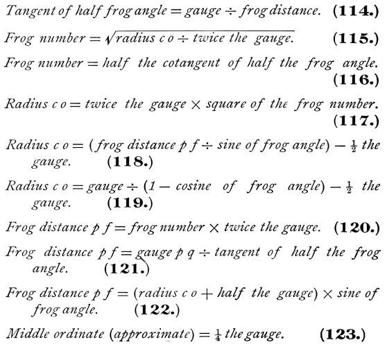
rails composing the frog are fastened to a plate of wrought iron
or steel a c d b by means of rivets through the rail flanges,
as shown in the figure. Square holes e, f are
1106
punched in the plate to receive the railroad spikes, which
are driven into the cross-ties supporting the frog, holding it
firmly in place. Plate frogs are perfectly rigid, and by many
railroad men are considered inferior to the keyed frog, shown
in Fig. 526, which is somewhat flexible
and better suited to yard work where the curves are sharp and
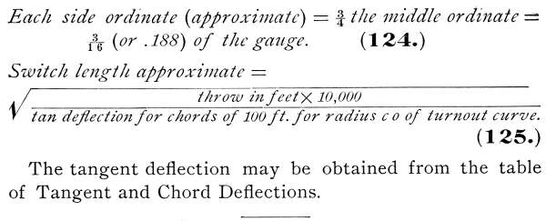
the frog angles correspondingly large.
In this frog, the pieces of rails a and b, forming
the point, are dovetailed together and secured by heavy rivets.
To retain the full strength and durability of the steel, all the
parts are fitted without being heated, excepting the wings, which
are bent at a very low heat. Hence, the strength of the rails
is in no respect diminished, and the method of securing the parts
together has advantages over bolts or rivets passing through the
webs or flanges of the rails, as there is nothing which can come
in contact with the wheel flanges. From its peculiar construction,
it has the same elasticity as the rails in the track, which makes
it an easy riding frog, more durable than a rigid frog, and less
liable to injury from uneven ballasting. It presents little obstruction
to tamping, and, when fastened into the track with the usual angle
splices, it is firm, stable, and free from any tendency to jump
or move.
The parts are bound together by heavy wrought-iron clamps c
and d, shown in the cross-sections A and B,
A being a cross-section through the, first clamp and B
one
1107
through the second clamp. These clamps are tightened
by means of beveled split keys, or wedges, e and f,
the ends of the clamps being bent over a form to an exact angle,
at one end to fit the brace blocks k and k' on the
outside of the rail, and at the other end to fit the beveled keys,
which are driven into the spaces between the end of the clamp
and the smaller brace blocks l, l'. The keys lie
on the flange of the rail, which prevents them from dropping down
in case they loosen. The flange way between the frog point and
the wing rails is maintained by iron throat-pieces g, h, g',
and h', which fit the rails perfectly, and, extending beyond
the point, thoroughly brace and stay it against lateral stresses.
After the keys are driven to the extent necessary to bind the
parts solidly together, the split ends are spread to prevent the
keys from working out.
The throat-pieces, as well as the brace blocks, are effectually
prevented from sliding out of their positions. The clamps are
firmly secured to the flanges of the rails, and the only movable
pieces in the frog are the keys which, being thicker on their
lower edge (owing to being beveled unequally), together with the
angles of the clamps, prevent the keys from working upwards. Trackmen,
when inspecting track, should always examine the frogs, and any
key loosened by the wearing of the parts should be tightly driven,
and the split end spread open. Unless a key is loose it should
never be hammered.
A standard type of a spring-rail frog of keyed pattern
is shown in Fig.
527. For main line tracks, and especially for those sections
where the heavy traffic moves principally in one direction, the
spring-rail frog is recommended. It gives to the main line the
smoothness of an unbroken track; it, is simple in its construction,
thoroughly substantial, and is placed in position with the least
amount of labor.
As shown in the figure, the fixed parts of the patent keyed
spring frog are bound together by two heavy clamps a and
b, shown in the details A and B, which are
sections through the clamps at C D and E F. The
parts within the clamps are secured by split keys or wedges c
and d. The frog point
1108
G is made of two pieces of steel rail fitted and dovetailed
together by machinery, without being heated, and securely riveted
together. The flange way between the point, and wing rails is
maintained by closely fitting iron throat-pieces e and
f (shown in the detail sections A and B),
which are prevented from slipping by rivets and pins through the
rails. The clamps have side notches g and g' at
one end (shown in detail at L), which engage with notches
in the flange at the frog point, and, prevent the clamps from
slipping down, even if loose. The other end of the clamp is bent
over a form to an exact angle to fit the beveled split key, which
is driven into the space between the clamp and the block, which
is fitted and secured to the side wing rail. When the key is driven,
the parts of
1109
the frog are tightly bound together, and the key resting
upon the flange of the rail is prevented from working down and
loosening. The outer end of the clamp is secured by clips, which
are riveted to the flange of the rail.
In case the parts of the frog become loosened by wear, they
may be tightened by driving the wedge further in and spreading
the split ends so as to hold the key firmly in place.
That part of the flange of the spring rail next to the frog
point is planed off, allowing the head of the spring rail to lie
close to the frog point, forming almost a continuous rail and
fully accommodating all classes of wheels passing the frog. Powerful
springs H and K hold the spring rail firmly against
the frog point, and the slide arm h, which is held in place
by the clip k, attached to the slide plate (shown in the
detail section M N), prevents the spring rail from
rising up or moving out too far. The usual length of this spring
frog for any angle is 15 feet.
1682. Crossing Frogs.—Where one railroad crosses
another at grade, frogs of special design, called crossing
frogs, are required. They are of various patterns, depending
upon the angle of the crossing and the importance of the line.
In Fig. 528
a cut is given of a standard crossing, which embodies the
best features as determined by experience.
This crossing is made of the best quality steel rails, fitted
with exactness. The points are mitered, dovetailed, welded, or
forged out of solid rails, the angle of the crossing and the requirements
of the case determining which method is the most practicable.
The rails are mounted on strong wrought-iron bed-plates A,
B, etc., to which they are securely riveted through the flanges
of the rails. The guard-rails a, b, c, and d, inside
the intersecting tracks, extend unbroken on all sides, and extend
outside the frog points so as to guide the trucks, causing them
to pass squarely through the crossing.
At all the angles the flange way is completely filled by wrought-iron
throat fillers e, f, and c, which are shaped to
exactly fit the rails.
1110
All the corners are braced with heavy wrought-iron braces g,
h, k, etc., forged to shape and planed to fit solid in
the fishing spaces of the rails. Strong bolts, 1, m, etc.,
passing through the webs of the rails, the throat fillers, and
corner braces, bind the parts of the crossing firmly together.
All the inside splice joints are provided with solid iron throat
blocks n, o between the rails in addition to the usual
splice bars. The splice bolts p and q pass through
splice bar, throat block, and rail, binding all securely together.
Care should be taken that no bolts project through the bed-plates,
necessitating the cutting of pockets in the crossing timbers to
receive the bolt heads, as increased decay is sure to follow.
1683. Replacing Frogs.—A replacing frog is a device
for replacing derailed cars upon the track. Such a frog must combine
portability and great strength. It must be flexible and compact,
and of simple construction.
The replacing frog shown in Fig. 529 combines practically all of these
qualities. This frog consists of a heavy steel bar a slightly
curved. The bar is bolted at one end to a heavy steel hook b
which hooks under the head of the rail. The joint c,
connecting the bar and hook, allows the frog to be placed in any
desired position. The end d of the bar is hooked and pointed.
In using the frog, the hook b is first adjusted; the end
d is then placed directly in front of the wheel of the
derailed truck, and the point d of the bar driven into
the cross-tic with a sledge. This holds the
1111
replacing frog rigidly in place. A replacing frog is placed
in position on both rails, and the car pulled on to the track
with a locomotive. Where the trucks are slewed crosswise to the
track, the car must be jacked tip and the trucks straightened
before placing the frogs.
SWITCHES.
1684. Classification of Switches.—Although there
have been many different kinds of switches devised, only two of
them have ever been in general use; viz., stub and split,
or point, switches. Stub switches are now rarely used on
first-class roads, even in yards, the split or point switch having
entirely supplanted them. It is estimated that 50 per cent. of
the derailments on American lines have been directly chargeable
to the defects of the stub switch.
The principal defect in the stub switch lies in the open joint
at the head-block. In passing over this joint, each wheel delivers
a heavy blow on the ends of the rails at the point, which not
only batters the rails but also causes a heavy jolt to the car,
injurious to the rolling stock and causing much discomfort to
passengers. Stub switches are more liable to misplacement than
split switches, and there is the constantly recurring need of
recutting the ends of the rails at the head-block, to provide
for expansion and for the removal of battered ends.
1685. The Stub Switch.—The essential parts of a
stub switch are shown at A in Fig. 530. The rails a b and c
d are the switch rails placed for the turnout track.
Their position when placed for the main track is indicated by
dotted lines at e and f. The switch rails are commonly
used in lengths of 30 feet, the standard rail length, of which
only 22 feet are free to move or slide, the remaining 8 feet being
spiked to the ties, as shown in the figure. The moving portions
of the switch rails are held in place by rods g, h, k,
and 1, called switch rods. These rods keep the switch
rails at proper gauge, and serve the purpose of track spikes.
1113
The first switch rod g is called the head
rod. It extends outside the rails, and by means of the connection
rod m, it is attached to the lever n of
the switch stand, by means of which the switch rails are moved
from their connection with the main track rails o and p,
to a connection with the turnout rails q and r. This movement
of the switch rails is termed throwing the switch.
The switch stand, and connection and head rods of this
switch are shown in detail at B. The switch stand D
consists of a cast-iron plate s to which is cast a semicircular
lug t. A hole in this lug receives a pin, which is attached
to the end of the lever n. The connection rod m
is attached to the lever by means of the pin u, and is
held in place by a nut. The lever handle is slotted, and when
the switch is set for either track, the slot fits over a staple
v, projecting above the lever far enough to receive a padlock
w which locks the switch.
The switch rods clamp the switch rails firmly, as shown at
x. The head chair, shown at E, is of cast
iron, and contains sockets y, y, into which the ends of
the main and turnout rails o and q securely fit.
The lateral movement of the switch rail is limited by the lugs
z and z', which are cast into the chair. The head
chair is usually fastened to the head-block with track spikes.
The cross-tie F, which supports the head chairs and
switch stand, is called the head block. The head block
and all other switch ties should be of hard wood—oak preferably.
The ties under the switch rails should be of sawed timber, so
as to present a smooth even surface for the sliding rails.
This type of switch stand is equally well suited to split switches,
and on account of its compactness is especially suited to yard
work.
The stub switch is cheaper than the split switch, and for tracks
owned by private concerns, it serves very well; but for railroads
doing a regular freight and passenger business, it is not only
out of date, but should be condemned as unsafe.
1115
1686. Split, or Point, Switches.—The split, or
point, switch does away with the open joint at the head block
and gives a continuous bearing to the car wheels. The two common
types of split switches are shown in Figs. 531 and 532. In Fig. 531,
the rails A A' and B B' are called the stock
rails. In the split switch, the heels and toes of the switch
rails are exactly the reverse of those in the stub switch, i.e.,
the heels in the split switch are in the places
occupied by the toes in the stub switch. The stock
rails are spiked throughout their entire length. The switch rails
C C', D D' are usually 15 feet in length for all turnouts
excepting those in yards where limited space requires very sharp
curves, and switch points 12 feet in length, or even less, are
used instead.
The switch rails are usually straight and planed down so as
to fit closely to the stock rails for 6 or 7 feet. The points
C and D are planed down to a thin edge, the web
of the switch rail being grooved so as to fit under the head of
the stock rail.
The base of the switch rail is planed so that it fits snugly
against the upper part of the base of the stock rail. The extreme
points of the switch rails are slightly below the level of the
stock rails, so that the wheel treads do not come in contact with
them until their size and strength are sufficient to stand the
hard pounding which all switches receive.
The slide plates a, b, c, d, e, and f extend
under the stock rails and points, and are spiked to the cross-ties.
The switch rods g, h, k, 1, and in are of wrought iron,
and of such dimensions as the size and weight of the rail require.
They are fastened to the switch rails in various ways. In Fig. 531, the connection is made by means
of cast steel sockets which are bolted to the webs of the rails.
The switch rod g, connecting directly with the switch stand,
is called the head rod, and is shown in detail at E.
The cast-steel sockets n and n' are longer, and
extend low enough to permit the head rod to pass under the rails,
as shown in the detail. The head rod is fastened to each socket,
with two bolts, while the other switch rods are single bolted.
1116
The stock rails are spiked only on the outsides of the rails,
and to prevent the rails from getting out of line, the slide plates
are bent upwards at the outside of the rail, forming the lip o
(see detail at F), which holds the rail brace p
solidly against the stock rail.
The connection rod q is fastened at one end to the head
rod and at the other end to the crank r of the switch stand,
shown in detail at G. The switch stand rests upon two cross-ties
s and s', being securely fastened to them either
with bolts or track spikes. The switch stand consists of the column-shaped
support t, the lever u, used in throwing the switch,
the target v, and the crank-shaft r.
The target v consists of two rectangular pieces of sheet
iron fastened to the target rod at right angles to each other.
One-half of the target is usually painted white, indicating
safety, and the other half red, indicating danger.
They are so adjusted that an open switch always indicates
danger
The lever u carries a cam or eccentric-shaped
disk w which, when in the position u, fits between
lugs x; the lugs are bolted to the pedestal t, and
form a part of the rigid stand. When the lever is in the position
u, the switch may be locked, holding the switch firmly
in place. To throw the switch, raise the lever to the position
u'. This releases the cam w from the lug x,
and the lever being clamped to the target rod or shaft y,
any movement of the lever u is communicated to the crank
r, which, by means of the connection rod q, acts
directly upon the switch rails.
The throw of the switch is from 4½ to 5 inches. The
rail braces p are usually of forged steel, though some
are still made of cast iron.
1687. Safety Switches.—When a train passes from
the main track to the side track, it necessarily passes the points
of the switch first. Such a switch is called a facing switch.
When, on the other hand, a train passes from the side track
to the main track, it passes the frog first. Such a switch is
called a trailing switch.
1118
William Lorenz, chief engineer of the Philadelphia and Reading
Railroad, has the credit of designing a self-acting switch, which
is provided with a powerful spring that holds the switch points
firmly against the stock rail, thus keeping the main track constantly
unbroken. With the switch points in this position, a train can
make a trailing switch, the wheel flanges forcing the switch open
as they pass from the side to the main track. As the spring is
constantly acting, each wheel throws the switch, which instantly
resumes its position for the main track.
Such a switch is called a Lorenz, or safety switch,
and is shown in Fig. 532. With
the exception of the spiral spring A, which is attached
to the head rod and holds the switch point a against the
stock rail b, this switch is similar to that shown in Fig. 531.
The switch rods c, d, and e, instead of being
single rods with arms at their ends for attaching them to the
switch rails, as in Fig. 531, have
a trussed center piece, shown in detail at B, composed
of two bars f and g, riveted together and leaving
between them just space enough to allow the ends of the arms h
and k to move as the switch is thrown from one side of
the track to the other, the arms pivoting on the rivets l
and m at the end of the center piece.
This form of switch rod combines flexibility with great strength,
insuring easy movement to the switch and great resistance to the
severe stresses which are continually brought to bear against
it.
The switch rods are bent downwards near the arms, bringing
them nearly on a level with the top of the tie, where they are
less exposed to injury from derailed cars or from broken parts
of the cars, such as brake rods or beams, which dragging on the
ties frequently catch in switch rods, doing much harm.
The safety switch, shown in Fig. 532,
is of a pattern commonly used in yards and terminals. The switch
points vary in length from 7½ feet to 12 feet, the former
fitting all frog numbers as high as 7, and the latter serving
for frogs of all numbers.
1119
The advantages of this switch are its compactness, requiring
little more than half the space of an ordinary switch; lightness,
which insures easy handling, and its adaptation to sharp curves
which abound in yards and terminals. The short points permit of
trailing switches equally as well as facing switches, as the planed
portion of the points is short, and, consequently, carries a much
shorter proportion of the wheel base of an engine or car than
the switch of the standard length. The short points also require
lighter springs than the standard lengths, and are much easier
cleared of snow. The details of the switch are practically the
same as those of the switch shown in Fig.
531, which were fully described. A common yard stand suitable
for this switch is shown in both plan and elevation at C.
The target is about 4 feet above the ground, and is provided with
an attachment for signal lamp. The lever is hinge-jointed, and
in throwing the switch, the lever is brought into a horizontal
position, resting on the semicircular iron latch plate E.
In the edge of this plate are two slots n and o,
into which the lever hinges after the switch is thrown. Lugs p
and q at the sides of the slots, limit the lateral movement
of the lever. The switch stand is secured to the head-block by
either bolts or track spikes, usually the latter.
1688. Three-Throw Switches.—A cut of a three-throw,
or double-throw, switch is given in Fig. 533. The type is that of the ordinary
stub switch, except that the moving or switch rails serve two
turnout tracks instead of but one. The head chair A is
usually of cast iron and contains sockets a, b, and c
(see detail B) for the fixed rails d, e,
and f.
The switch rails g and h have a total lateral
movement at the head chairs of from 10 to 12 inches, depending
upon the dimensions of the rails. Their lateral movement is fixed
by the lugs k, k on the head chairs.
The switch stand is shown in elevation at C, and in
plan at D. The three positions of the switch are fixed
by the slots l, m, and o in the latch plate
into which the switch lever hinges.
1120
A more comprehensive idea of a double-throw switch may be obtained
from the detail given at E, which shows to a reduced scale
the switch and both turnout curves with main rail frogs p
and v, and the crotch frog r, by means of
which
1121
the outer rails of the turnout curves cross each other. The
turnout curves of a double-throw switch are usually of the same
degree, which brings the crotch frog in the middle of the main
track.
The defects of the stub switch already described should prevent
its use in the main track at yards, and at terminals where trains
move slowly, as well as at intermediate points where trains run
at top speed.
A double-throw split switch has been invented and used
in a limited way, and though a perfect switch so far as mechanism
is concerned, it is much more expensive and complicated than a
double-throw stub switch, and is not enduring.
The object of the double-throw switch, viz., economy of space,
is practically attained by substituting two single split switches,
placed as close together as is consistent with their safe operation.
Such an arrangement is shown in Fig. 534, in which a a' and b
b' are the rails of the main track. A 7° 30' turnout curve
c e is laid out to the right of the main track. This calls
for ahead block at c and a No. 9 frog at f.
A 17 degree turnout curve g m is next laid out
to the left of the main track, with its P. C. located so as to
bring the head block g of the second switch far enough
from the heel d of the first switch to afford sufficient
room for operating the second switch. This calls for a No. 6 frog
at k and a No. 5½ crotch frog at l.
1689. Derailing Switches.—A derailing switch is
a device for derailing cars, and so preventing them from accidentally
running out of the siding on the main track.
1123
They are, of course, needed only for sidings built with grades
descending towards the switch.
An effective type of a derailing switch is shown at A
in Fig. 535.
It consists of a single switch rail a, which is hinged
at the rail joint b. The switch point c is beveled,
as shown in the detail at C. When the switch is closed,
this beveled switch point rests against the outside rail of the
siding, which is bent at an angle corresponding to the bevel of
the switch point and shown at d, forming a lap switch.
When the switch is open, the switch point rests against the
guard rail e, the end of which is beveled to form a seat
for the switch point. The beveled ends of both track and guard
rail rest upon a wrought-iron head chair f, shown in detail
at C, upon which the switch point slides.
This switch is connected with and operated by the movement
of the main line switch B. The figure shows the switch
set for the main line, and the derailing switch set to
throw from the track a car moving out of the siding.
The derailing switch is operated as follows: A bell-crank g
is pivoted to a cross-tie, with one end of the crank attached
to the head rod of the switch B. To the other end
of the crank is attached a strong steel wire which extends to
a sheave h, directly opposite the derailing switch A,
and thence to an eye k, as shown in detail at C
and D, in the end of the head rod. This wire is kept taut,
so that any movement of the switch B is communicated
directly to the switch rail a. The connection rod l
is attached to the short arm m of the switch lever; and
when the switch is set for the main line E E, as shown
in the figure, the resulting stress in the wire is transmitted
to the short arm m of the derailing switch lever; the long
arm of the lever which carries the weight o is then brought
into the position n, and the switch rail or point takes
the position a (see detail C), leaving the derailing
switch open and protecting the main track from runaway cars.
When, on the other hand, the switch is placed for the siding
E F, the tension on the wire is relaxed and the long arm
n of the derailing switch lever, being acted upon by the
1124
weight o, is made to take the position n', and
the short arm of the lever, the position m'. This movement
is transmitted by the connection rod to the switch rail, which
takes the position a' (see detail C), securely closing
the switch. The guard rail e is secured to the main rail
p by two heavy bolts, the space between them being maintained
by a cast-iron throat filler q. Near the derailing switch,
a guard rail r is placed, diverging from the outside rail,
the object of which is to prevent derailed cars from running on
to the main line. A heavy plank s is spiked to the ties
close to the outside rail to prevent any derailed trucks from
turning up the rails.
1690. Automatic Turnouts.—For dummy or
street car roads using a light T
rail, the automatic switch shown in Fig. 536 may be used on turnouts, or passing
tracks, to great advantage. There are two switch points a
and b, one of which, a, is rigid, forming a combination
of frog and switch point. It consists of a guard rail c, two throat
fillers d and e, and the switch point a.
The throat fillers between the switch point and the head block
unite, forming a single filler, which is grooved at f.
When
1125
approaching or leaving the switch, the wheel flange enters
this groove, bringing the wheel tread safely upon the stock rail
g.
In America, at least, it is the universal custom for cars approaching
a passing track to take the right-hand track in the direction
indicated in the figure by the arrows m and n. Accordingly
the switch is always set for the right-hand track, the switch
point b being held firmly against the stock rail h
by means of the iron rod k, which is acted upon by a powerful
spring confined in the shell l. This shell is spiked to
the head block between the rails, as shown in the figure, and
hence is not an obstruction to travel, as it would be if placed
outside the rails, and it is also comparatively safe from injury
from the wheels of heavy trucks and drays.
A car moving in the opposite direction, as indicated by the
arrow o, throws the switch automatically. As the wheel
flanges come in contact with the switch rail b, the spiral
spring which holds the switch rail in place yields to the pressure,
and the switch opens, allowing the car to pass from the siding
to the main track. The wheel flanges, after passing the
switch point a, enter the groove f, before mentioned,
and the wheel treads pass safely on to the stock rail g.
As the spring is constantly acting, each wheel throws the switch,
which closes the instant the wheel flange passes the point.
There are three forms of turnouts, or passing tracks, in general
use; they are shown in Fig.
537, at A, B, and C,
1126
the arrows indicating the direction in which cars enter and
leave the turnout. It will be seen that some one of these three
forms of passing tracks will meet practically any given situation.
That shown at B is particularly suited to track laid along
the side of a street or highway, which may be widened at the points
requiring passing tracks. The form shown at C should always
be adopted for tracks laid on the center line of streets. The
extra room required for passing tracks is equally distributed
on both sides of the main center line of the street, so that there
will be the least possible encroachment upon the space left for
vehicles.
1691. Y Tracks.—The form of turnout shown in Fig. 538 is
called a Y. It is used as a substitute
for a turntable. Sometimes the switches are automatic, as shown
in the figure, in which case all locomotives must enter the Y from the same end, viz., at a,
and leave at b. Usually, however, the switches are operated
by hand levers and the Y is entered
from both directions. One special advantage of a Y
track is that both engine and train may be turned together, and
where favorably situated, they are much used in shifting light
trains which are run at frequent intervals for the accommodation
of suburban travel.
1127
1692. The Parts of a Turnout.—The several parts
of a turnout are represented in Fig. 539. The distance p f from
the P. C. of the turnout curve to the point of frog is called
the frog distance. The frog number and frog angle we have
already defined. The radius c o of the turnout curve,
the frog distance, the frog angle, and the frog number bear certain
relations to each other, which are expressed by the following
formulas:
1128
1129
The switch lengths in the above table merely denote the shortest
length of stub switch that will at the same time form
part of the turnout curve, and give 5 inches throw. Point or
split switches require a throw of not more than 3½
inches, though many have a throw of 5 inches, with an equal space
between the gauge lines at the heel. The heels of a split switch,
which occupy the same position as the toes of a stub switch, should
be placed at the point where the tangent deflection or offset
is 5 inches. The point where the tangent deflection is but 4½
inches will answer for many rail sections, but for those above
65 lb. per yard, 5 inches should be taken.
In the table of Tangent and Chord Deflections, tangent deflections
for chords of 100 feet are given for all curves up to 20 degrees,
and for a curve of higher degree, the tangent deflection may be
found by applying formula 93, Art. 1255, tan
deflection = c²/2R.
In complicated track work where space is limited, curves must
be chosen to meet the existing conditions, and not with reference
to particular frog angles, in which case the frogs are called
special frogs, and are made to fit the particular curve used.
The determination of the frog distance, switch length, and frog
angle may be understood by referring to Fig. 540 (next page).
Let the main track a b be a straight line; the gauge
p q = 4 feet 8½ inches (= 4.71 feet); the degree
of the turnout curve =13 degrees; the chord q d = 100 feet;
c d = the tangent deflection of the chord q d, and
p f = the frog distance. From the table of Tangents and
Chord Deflections, we find the tangent deflection for a chord
100 feet long of a 13 degree curve is 11.32 feet.
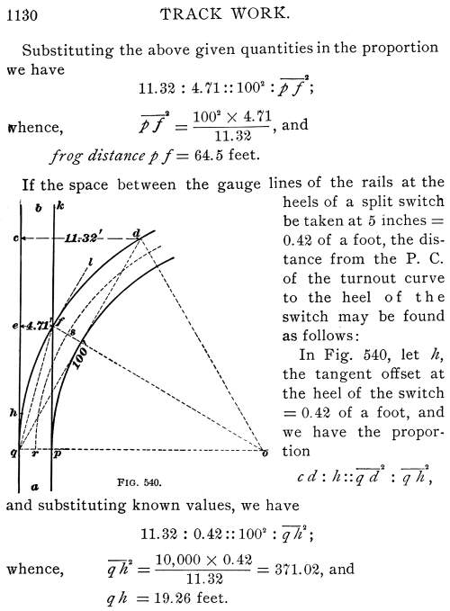
This locates the heel of a split switch and the toe
of a stub switch.
The frog angle is the angle k f l (see Fig. 540) formed
by the gauge line of the main rail f k and the tangent
to the outer rail q f of the turnout curve at the point
where the two rails intersect. This angle is equal to the central
angle q o f. The arcs q f and r s are assumed
to be of the same length. The turnout curve being 13°, the
central
1131
13 x 60 angle for a chord of 1 foot is 13 x 60/100 = 7.8',
and the central angle for 64.5 feet, the frog distance,
is 7.8' x 64.5 = 8° 23', the frog angle for a 13 degree curve.
By this process the frog distance, switch length, and frog angle
may be calculated for curves of any radius.
1693. To Lay Out a Turnout from a Curved Main Track.—There
are two cases:
Case I.—When the two curves deflect in opposite
directions, illustrated by Fig.
541, and
Case II.—When the two curves deflect in
the same direction, illustrated in Fig. 542.
In Fig. 541, the curve a b is
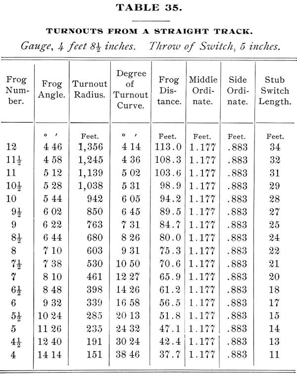
3 degrees 30', and it is proposed to use a No. 8 frog. By
reference to Table
35, we find that the degree of curve corresponding to a No.
8 frog is 9° 31'. Accordingly, we use a turnout curve a
e, whose degree when added to the degree of curve of the main
track shall equal the degree required for a No. 8 frog, i.e.,
we use a 6° turnout curve, which is within one minute of the
required
1132
degree, and close enough for practical purposes. From our knowledge
of tangent and chord deflections we know that for curves of moderate
radii, i.e., from 1 degree up to 12 degrees, the tangent deflections
or offsets increase as the degree of the curve. That is, the tangent
deflection of a 2 degrees, 4 degrees, and 6 degree curve is two,
four and, six times, respectively, that of a 1 degree curve. In
the accompanying figures illustrating the location of frogs and
switches, each curve is represented by two lines indicating the
rails, whereas only the center lines of the curves are run in
on the ground. In Fig. 541, the line
c d is tangent to the center lines of the curves. These
center lines do not appear in the cut.
Now, if, in Fig. 541, a tangent
c d be drawn at c, the point common to the
center lines of the curves, the sum of the deflections of both
curves from the common tangent will be equal to the tangent deflection
of a 9° 30' curve from a straight line.
Accordingly, to find the frog distance for a 6 degree turnout
curve from a 3 degree 30' curve, the curves being in opposite
directions, as shown in Fig. 541, we
find the tangent deflection of a 9 degree 30' curve for a chord
of 100 feet. This deflection is 8.28 feet (see table of Radii
and Deflections). Assuming the gauge of track to be standard,
viz., 4 ft. 8½ in. = 4.71 ft., and denoting the required
frog distance by x, we have the following proportion:
8.28 : 4.71 :: 100² : x²;
whence, x² = 10,000 x 4.71/8.28 = 5.688.4, and
frog distance x = 75.42 feet.
We use the tangent deflection for a 9° 30' curve, which
is practically the same as for a 9° 31' curve, and so save
the labor of a calculation, which will not appreciably affect
the result.
We locate the heel of the switch in the same way, using for
the second term of the proportion 0.42 foot, the distance between
the gauge lines at the heel, instead of 4.71 feet, the gauge of
the track.
1133
In Fig. 542, which comes under Case
II, both curves deflect in the same direction, and the
rate of their deflection from each other is equal to the rate
of the deflection of a curve whose degree is equal to the difference
of the degrees of the two curves from a tangent.
Let the main track curve a b be 5 degrees, and the turnout
curve a c be 10 degrees. Then the rate of deflection or
divergence of the 10° curve from the 5° curve is equal
to the divergence of a (10 degrees - 5 degrees) 5 degree curve
from a straight track or tangent.
Accordingly, we find, in the table of Radii and Deflections,
the tangent deflection for a 5° curve for a chord of 100 feet
= 4.36 feet. Denoting the required frog distance by x,
we have the following proportion:
4.36 : 4.71 :: 100² : x²;
whence, x² = 10,000 x 4.71/4.36 = 10,802.8, and
frog distance x = 103.9 feet.
Distances are not calculated nearer than to tenths of feet.
1694. How to Lay Out a Switch.—In laying
out a switch, locate the frog so as to cut the least possible
number of rails. Where there is some latitude in the choice of
location, the P. C. of the turnout curve can be located, so as
to bring the frog near the end of a rail.
To do this, take from Table 35
the frog distance corresponding to the number of the frog to be
used. Locate approximately the P. C. of the turnout curve, and
measure from it along the main track rail the tabular frog distance.
If this brings the frog point near the end of the rail, the P.
C. of the turnout curve may be moved so as to require the cutting
of but one main track rail. Measure the total length of
the frog and deduct it from the length of the rail to be cut,
marking with red chalk on the flange of the rail the point at
which the rail is to be cut. Measure the width of the frog at
the heel and calculate the distance from the heel to the theoretical
point of frog. For example, if the width of the frog at the heel
is 8½ inches, and a No. 8 frog
1134
is to be used, the theoretical distance from the heel to the
point of frog is 8.5 x 8 = 68 inches = 5 feet 8 inches. Measure
off this distance from the point marking the heel of the frog.
This will locate the point of frog, which should be distinctly
marked with red chalk on the flange of the rail. It is a common
practice to make a distinct mark on the web of the main track
rail, directly opposite to the point of frog. This point being
under the head of the rail, it is protected from wear and the
weather. The P. C. of the turnout curve is then located by measuring
the frog distance from the point of frog. From Table
35 we find the frog distance for a No. 8 frog is 75.3 feet,
and the switch length, i.e., the distance from the P. C. of the
turnout curve to the heel of the split switch or toe of the stub
switch, is 22 feet.
If a stub switch is to be laid, make a chalk mark on
both main track rails on a line marking the center of the head
block. A more permanent mark is made with a center punch. Stretch
a cord touching these marks, and drive a stake on each side of
the track, with a tack in each. This line should be at right angles
to the center line of the track, and the stakes should be far
enough from the track as not to be disturbed when putting in switch
ties. Next, cut the switch ties of proper length; draw the spikes
from the track ties, three or four at a time, and remove them
from the track, replacing them with switch ties, and tamping them
securely in place. When all the long ties are bedded, cut the
main track rail for the frog, being careful that the amount cut
off is just equal to the length of the frog. If, by increasing
or decreasing the length of the lead 5 per cent. you can avoid
cutting a rail, do not hesitate to do so, especially for frogs
above No. 8.
Use full length rails (30 feet) for moving or switch rails,
and be careful to leave a joint of proper width at the head chair.
Spike the head chairs to the head block so that the main track
rails will be in perfect line. Spike from 8 to 10 feet of the
switch rails to the ties, and slide the cross rods on to the rail
flanges, spacing them at equal intervals.
1135
The cross rods are placed between the switch ties, which should
not be more than 15 inches from center to center of tie. The switch
ties, especially those under the moving rails, should be of sawed
oak timber. Southern pine is a good second choice. Attach
the connection rod to the head rod and to the switch stand. With
these connections made, it is an easy matter to place the switch
stand so as to give the proper throw of the switch.
It is common practice to fasten the switch stand to the head
block with track spikes, but a better fastening is made with bolts.
The stand is first properly placed and the holes marked and bored,
and the bolts passed through from the under side of the head block.
This obviates all danger of movement of the switch stand in fastening,
which is liable to occur when spikes are used, and insures a perfect
throw.
The use of track spikes is quite admissible when holes are
bored to receive them, in which case a half-inch auger should
be used for standard track spikes. The switch stand should, when
possible, be placed facing the switch, so as to be seen from the
engineer's side of the engine—the right-hand side.
Next stretch a cord from a, Fig. 543, a point on the outer main track
rail opposite the P. C. of the turnout curve, to b, the
point of the frog. This cord will take the position of the chord
of the arc of the outer rail of the turnout curve. Mark the middle
point c and the quarter points d and e. Whatever
the degree of the turnout curve, the distance from the middle
point c of the chord to the are a b is 1.18 feet,
and the distances from the quarter points d and e are
.88 foot; hence, at c lay off the ordinate 1.18 feet, and
at both d and e the ordinate .88 foot, three-quarters
of the middle ordinate. These offsets will mark the gauge line
of the rail a b. Add to these off sets the distance from
the gauge line to outside of the rail flange,
1136
and mark the points on the switch ties. Spike a lead rail to
these marks and place the other at easy track gauge from it. Spike
the rails of the turnout as far as the point of frog to exact
gauge, unless the gauge has been widened owing to the sharpness
of the curve. Beyond the point of frog the curve may be allowed
to vary a little in gauge to prevent a kink showing opposite the
frog. In case the gauge is widened at the frog, increase the guard
rail distance an equal amount. For a gauge of 4 feet 8½
inches, place the side of the guard rail which comes in contact
with the car wheels at 4 feet 6-and-five-eighths-inches from the
gauge line of the frog. This gives a space of 1-and-seven-eighths
inches between the main rail and the guard rail.
In case the gauge is widened ¼ or ½ inch increase
the guard rail distance an equal amount.
When the turnout curve is very sharp, it will be necessary
to curve the switch rails, to avoid an angle at the head block.
The lead rails should be carefully curved before being laid, and
great pains taken to secure a perfect line.
If a point, or split, switch is to be
laid, the order of work is nearly the same. The same precautions
must be taken to avoid the unnecessary cutting of rails, with
the additional precaution of keeping the switch points clear of
rail joints, as the bolts and angle splices will prevent the switch
points from lying close to the stock rails. As already stated,
these conditions can usually be met Where there is some range
in the choice of the location of the switch. Where there is none,
the main track rails must be cut to fit the switch.
Having located the point of frog, the P. C. of the turnout curve,
and the heel line of the switch, measure back from the heel line
a distance equal to the length of the switch rails, and place
on the flange of each rail a chalk mark to locate the ends of
the switch points. This will also locate the head block. Prepare
switch ties of the requisite number and length, and place them
in the track in proper order. As in
1137
the case of stub switches, see to it that all long switch
ties are in place before cutting the rail for placing the frog;
also, that the ends of the lead rails, with which the switch points
connect, are exactly even; otherwise the switch rods will be skewed,
and the switch will not work or fit well. Fasten the switch rods
in place, being careful to place them in their proper order, the
head rod being No. 1. Each rod is marked with a center punch,
the number of the punch marks corresponding to the number of the
rod.
Couple the switch points with the lead rails and place the
sliding plates in position, securely spiking them to the ties.
Connect the head rod with the switch stand, and close the switch,
giving a clear main track.
Adjust the stand for this position of the switch, and bolt
it fast to the head block. Next, crowd the stock rail against
the switch point so as to insure a close fit, and secure it in
place with a rail brace at each tie; then continue the laying
of the rails of the turnout.
If there is no engineer to lay out the center line of the turnout,
the section foreman can put in the lead from ordinates, as explained
in Fig. 543. In modern railroad practice,
however, most track work is done under the direction of an engineer,
in which case the center line of the turnout is located with a
transit. This ensures a correct line and expedites work. For ordinary
curves, center stakes at intervals of 50 feet are sufficient,
excepting between the P. C. of the turnout and the point of frog,
where there should be a center stake at each interval of 25 feet.
Place a guard rail opposite the point of frog on both main track
and turnout. The guard rail should be 10 feet in length; this
is an economical length for cutting rails, as each full-length
rail makes three guard rails.
Two styles of guard rails are shown in Fig. 544. That shown at B is in
general use, but the style shown at A is growing in favor.
The latter is curved throughout its entire length. At its middle
point a, directly opposite the point of frog, the
1138
guard rail is spaced 1-and-seven-eighths inches from the gauge
line of the turnout rail b c. From this point the guard
rail diverges in both directions, giving at each end a flange-way
of 4 inches. This allows the wheels full play, excepting at the
point of frog, where the guard rail is exactly adjusted to the
track gauge, and holds the wheels in true line, preventing them
from climbing or mounting the frog. The style of
guard rail shown at B, though still much used, has two
objectionable features, viz., first, the abruptly curved ends
d and e often receive an almost direct blow from the wheel flanges,
which causes a car to lurch violently; and second, the flange-way
of uniform width, though proper for the main track when straight,
as in Fig. 544, is unsuited for sharp
curves on either a main track or a turnout, as it compels the
wheels to follow a curved line; whereas, the normal position of
the wheel base of each truck is that of a chord of, or a tangent
to, the curve. These two defects alone produce what is known as
a rough-riding frog, even though the frog is well lined
and ballasted.
It is customary to bend the stock rail with a rail bender in
the proportion of about 1 to 40, placing the angle about 10 inches
back from the switch points, so that the beveled points will lie
snugly against the stock rail. Exception to this rule is found
in the practice of the Philadelphia and Reading R.R., where the
switch points are curved so as to fit the stock rail, which is
not bent at the switch point, but laid to an exact curve.
The custom of half spiking side tracks should be condemned
as unsafe and very poor economy. Side tracks should receive as
thorough work as the main line, though, of course, they require
less of it. This point has been touched upon before.
1139
1695. Laying Frogs in Track.—In placing
a frog in the track, special care should be taken to put it in
perfect line and surface with the rails with which it connects.
Couple the frog to the main track rails and put them in perfect
line before spiking. This is more certain to give a true line
to the frog than to spike the connecting rails before coupling
with the frog. If the main track is in poor line, put in track
centers for lining the frog, for it is very difficult to correct
defects in line after a switch is once in place. Having spiked
the frog in place, put the rail opposite the frog in perfect gauge
for the full length of the frog, if on a tangent, and at the point
of frog, if on a curve. To have a frog in perfect gauge, try the
gauge at each end of the frog, and at about six inches back of
the frog point.
If the curve is very sharp and laid to a uniform gauge throughout,
an ugly kink is left opposite the frog. This defect is caused
by the frog rail, which is necessarily straight, and can be remedied
by spiking the rail to gauge only at the point of frog,
and allowing it to assume its natural curve for the remainder
of the frog's length.
Turnout curves of long radii require long frogs, and
the track can be spiked to proper gauge throughout its length
without any perceptible kink at the frog.
Long frogs and long leads are the best where it is practicable
to use them. The wear from sharp curves and short frogs, both
upon rails and rolling stock, is great, and they are to be used
only where limited space requires them.
1696. Switch Timbers.—Every first-class railroad
has its own standards for switches, which include the necessary
switch timbers. The following rule will answer well for general
use:
Rule.—To find the number of
ties required for any switch lead, reduce to inches the distance
from the head-block to the last long tie behind the frog, and
divide this distance by the number of inches from center to center
of tie; the quotient will be the number of ties required.
1140
EXAMPLE.—The distance from the head block to the
last tie behind the frog is 77 feet. The ties are spaced 21 inches
center to center. What is the number of ties required for the
switch?
SOLUTION.—77 feet = 924 inches; 924 ÷ 21
= 44, the number of ties required. Ans.
Switch ties should be 10 inches in width and at least 6 inches
in thickness, though 7 inches is preferable. The head-block should
be 12 inches in width and 8 inches in thickness, and 16 feet in
length. When timber may be furnished in odd lengths, the following
list will furnish the necessary timber for a given switch, which
is a single throw, and requiring a No. 8 frog:
SWITCH TIES 21 INCHES TO CENTER.
1 head-block 8" x 12" x 16' long.
8 pieces 6" x 10" x 9' long.
8 pieces 6" X 10" X 10' long.
8 pieces 6" x 10" x 11' long.
5 pieces 6" X 10" X 12' long.
5 pieces 6" x 10" x 13' long.
5 pieces 6" X 10" x 14' long.
3 pieces 6" X 10" x 15' long.
When even lengths only can be ordered, the list must be modified,
only care must be taken to have the timber long enough.
Switch ties in important yards should not be more than 9 inches
apart, if they are to be kept in proper surface. It is poor economy
to use inferior timber for switch ties, or a scant number of ties.
Switch building is expensive work, and should be made as permanent
as is practicable.
To cut switch ties the proper length apply the following rule:
Rule.—Measure the length of
the tie next the head block and the length of the last long tie
behind the frog. Find the difference in inches between them. Divide
this difference by the number of ties in the switch lead; the
quotient will be the increase in length per tie from the head
block towards the frog to have the ends of the ties in proper
line on both sides of the track.
1141
EXAMPLE.—The length of the tie next the head block
is 8 feet 6 inches = 102 inches. The length of the last tie behind
the frog is 15 feet = 180 inches. The, difference between the
lengths of the ties, 180 – 102 = 78 inches, which, divided
by 44, the required number of ties, gives 1.8, say 1¾ inches,
the average increase in length per tie.
There is nothing gained by giving to switch ties a greater
projection outside the rails than ordinary track ties. They add
to the labor of raising the track, are unsightly, and labor is
wasted in tamping up the long ends. The switch ties should be
cut to proper length, marked with chalk in consecutive numbers,
and a mark for the outside flange of the main track rail placed
on each tie for lining them. Any one acquainted with track work
knows that the labor of cutting ties to exact length, numbering
them, and marking them for, proper lining is labor saved. There
is then no time wasted in cutting and trying; the work can be
pushed from start to finish, and the result is a perfect piece
of work.
1697. Tamping Switch Ties.—Before tamping up a
set of switch ties, raise the track to a uniform surface. Tamp
the ties under the frog and main track rail first, raising the
frog a shade higher than the rest of the switch. The head block
should also be about one-quarter of an inch above the common surface,
especially if a stub switch, as the continual jarring caused by
wheels passing the open, joint will cause the head block to settle
slightly. Tamp up the middle of the ties first and then the outer
ends. This will prevent any sagging of the ties at center and
a corresponding rise at the ends. If possible, complete the tamping
before a train passes the switch.
1698. Three-Throw Switch Timbers.—The lengths of
switch timbers for a three-throw switch are found by doubling
the lengths of those for a single turnout, and subtracting from
each the length of the standard cross-tie.
1142
Before placing them in the switch, draw a chalk line across
the middle of each tie, and number them in the same order as in
a single turnout. Then, place them under the main track rail,
and make the middle mark of each switch tie coincide with the
middle point of the track gauge placed on the main track above
the tie.
1699. Location of Crotch Frog.—A crotch, or middle,
frog is a frog placed at the point where the outer rails of both
turnouts of a three-throw switch cross each other. When both turnouts
are of the same degree, the crotch frog comes midway between the
main track rails. Its location and angle may be determined as
follows: Let the turnout curves A and B, Fig. 545, be each 9° 30', uniting
with the main track C by a three-throw switch. Let a
be the P. C. common to both curves, and b, the location
of the crotch or middle frog.
It is evident that the point of the crotch frog should be exactly
midway between the gauge lines of the main track rails, and if
the gauge is 4 feet 8½ inches = 4.71 feet, the point of
the crotch frog will be 4.71/2 = 2.35 feet from each rail. Now,
the problem is to find the frog distance from a, the P. C., to
the point c, where the tangent deflection will equal 2.35, or
half the gauge. From the table of Radii and Deflections, we find
the tangent deflection of a 9° 30' curve is 8.28 feet. Applying
the principle explained in Art. 1692
1143
and Fig.
540, and letting x represent the required frog distance,
we have the following proportion:
8.28 : 2.35 :: 100² : x²;
whence, x² = 100² x 2.35/8.28 = 2,838.2 feet,
and x = 53.3 feet, nearly,
the required frog distance.
Now, there are two curves starting at the common point a;
the outer rails intersect at b, and the angle d b e,
formed by tangents drawn to the point of intersection, is
the angle of the crotch or middle frog. The angle is equal to
the sum of the angles a f b and a f' b; that is,
equal to double the central angle of either curve between the
P. C. and the point of intersection b. The degree of the
curve is 9° 30' = 570', and the central angle or total deflection
for each foot is 570'/100 = 5.7', and for the frog distance of
53.3 feet, the central angle is 53.8 x 5.7 = 303.8' = 5° 03.8'.
The angle of the crotch frog is double this angle, i.e., 5°
03.8' x 2 = 10° 07.6'. The crotch frog should be accurately
located and spiked in place before the lead rails are placed.
The one objection to the three-throw switch is the open joint
at the head block, the inevitable attendant of the stub switch,
but its advantages are so great that it will continue to be used,
especially in yard service.
1700. Cross-OverTracks.—A cross-over is
a track by means of which a train passes from one track to another,
The tracks united are usually parallel, as are the tracks of a
double track road. Such a cross-over is shown in Fig. 546. The tracks a b and c
d are 13 feet apart from center to center, which is the
standard distance for double tracks. The cross-over consists of
two turnout curves, e f and g h. These curves are
usually, though not necessarily, of the same degree. The curve
terminates at the points of frog f and h, between
which the track f h is a tangent. The essential point in
laying out a cross-over is to so place the
1144
frogs that the connecting track shall be tangent to both curves.
In Fig. 546, suppose the frogs are
No. 9, requiring 7° 31' turnout curves.
From Table 35, we find the required
frog distance is 84.7 feet, and the switch length 25 feet. As
previously noted, if there is considerable range in choice of
location, the frogs can be so placed as to largely avoid the cutting
of rails; but usually cross-overs are required at certain precise
places, and the rails must be cut as occasion demands. Having
located the point of frog at f, we determine the point
of the next frog at h, as follows: A No. 9 frog is one
which spreads 1 inch in width to every 9 inches in length, and
as the track between the frog points is straight, the distance
f h between these points will be as many times 9 inches
as is the space k between the tracks at the frog point
f. The main track centers are 13 feet apart, making the
space between the gauge lines of the inside rails 8 feet 3½
inches. As it is the rail l of the turnout which joins
the second frog at h, we subtract the gauge, 4 feet 8½
inches, from 8 feet 3½ inches, leaving 3 feet 7 inches,
the distance k,between the gauge line of the rail l,
opposite the frog point f, and the gauge line of the nearest
rail of the track c d. This distance multiplied by 9 inches
will give the distance from the frog point f to the frog
point h; 3 feet 7 inches = 43 inches, 43 x 9 = 387 inches
= 32 feet 3 inches. Accordingly having located the point of frog
f we mark a corresponding point on the nearest rail of
the opposite track. From this point we measure along the rail
the distance 32 feet 3 inches, locating the second frog point
h, and again the frog distance 84.7 feet to the P. C. of
the second turnout curve at g.
If frogs of different numbers, say 7 and 9, were to
1145
be used, the distance between the frogs is found as follows:
As the No. 7 frog spreads 1 inch in 7 inches, and the No. 9
frog 1 inch in 9 inches, the two will together spread 2 inches
in 7 + 9 = 16 inches, or 1 inch in 8 inches. Now, if the rails
to be united are 3 feet 7 inches, or 43 inches apart, as in the
previous problem, the distance between the frog points will be
43 x 8 = 344 inches = 28 feet 8 inches.
In locating cross-over tracks, regard should be paid to the
direction in which the bulk of the traffic moves, and the cross-over
tracks should be so placed that loaded cars will be backed, not
pushed, from one track to the other.
At all stations on double track roads there should be a cross-over
to facilitate the exchange of cars and the making up of trains.
Track Page
| Contents Page
|


